Apparatuses and methods for deploying logging tools and signalling in boreholes

Inactive Publication Date: 2007-04-10
REEVES WIRELINE TECH
View PDF32 Cites 66 Cited by
  • Summary
  • Abstract
  • Description
  • Claims
  • Application Information

AI Technical Summary

Benefits of technology

[0139]As noted hereinabove, these aspects of the method prevent potential damage to the components of apparatus carrying out the method of the invention by virtue of sudden deceleration of a large mass of borehole fluid and toolstring components.

Problems solved by technology

Consequently it is difficult to push or lower a wireline logging tool into a borehole having caved in or squeezed sections as aforesaid.
However the time taken to pump the messenger sub from an uphole location to approximately the TD of the well can be significant, not least because most oil wells are many hundreds or thousands of meters long.
Such preparation of the drillpipe is also time-consuming.
There is however a greater need for communication between downhole and uphole loca

Method used


Image

  • Apparatuses and methods for deploying logging tools and signalling in boreholes
  • Apparatuses and methods for deploying logging tools and signalling in boreholes
  • Apparatuses and methods for deploying logging tools and signalling in boreholes

Examples


Embodiment Construction

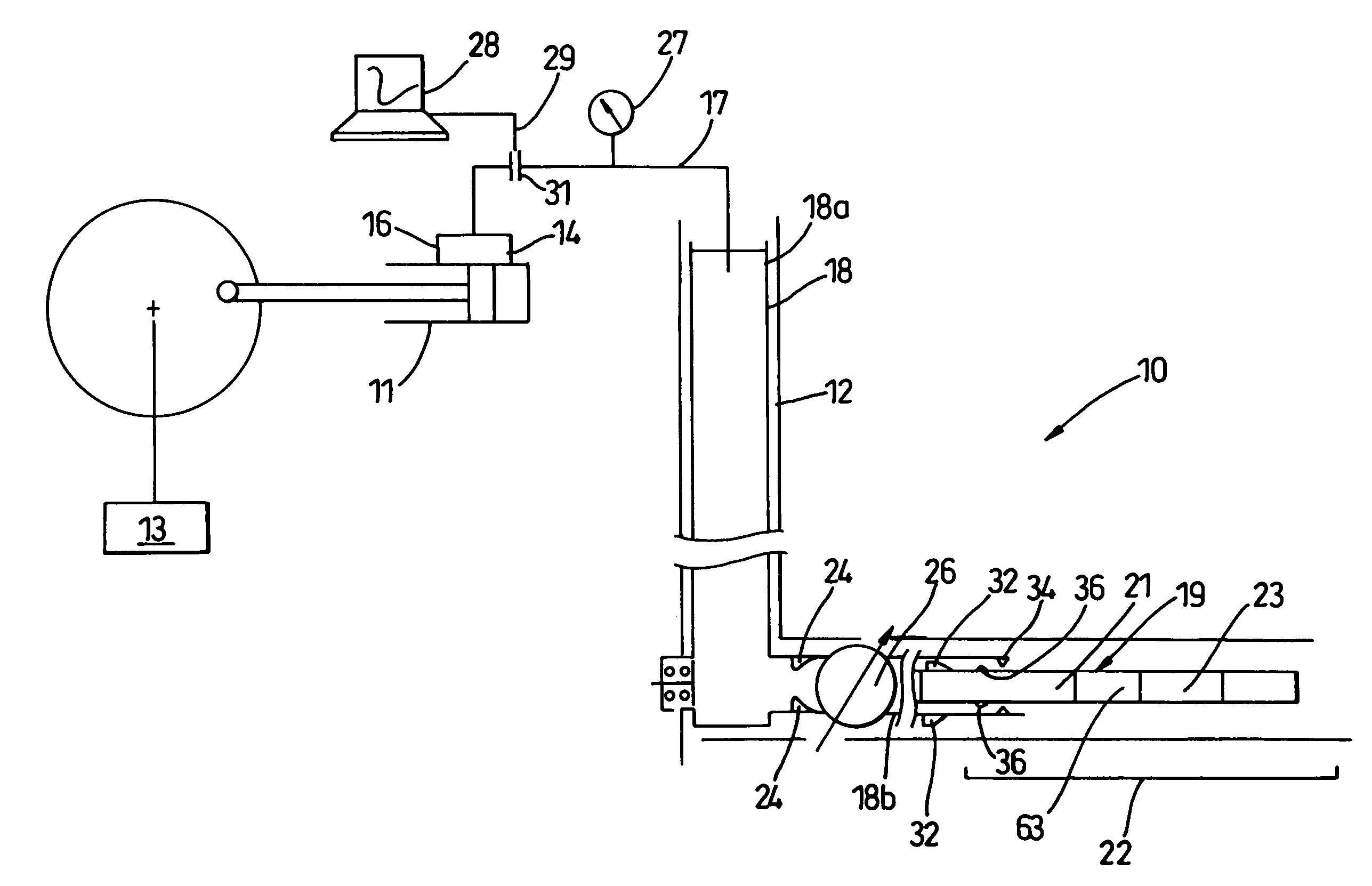
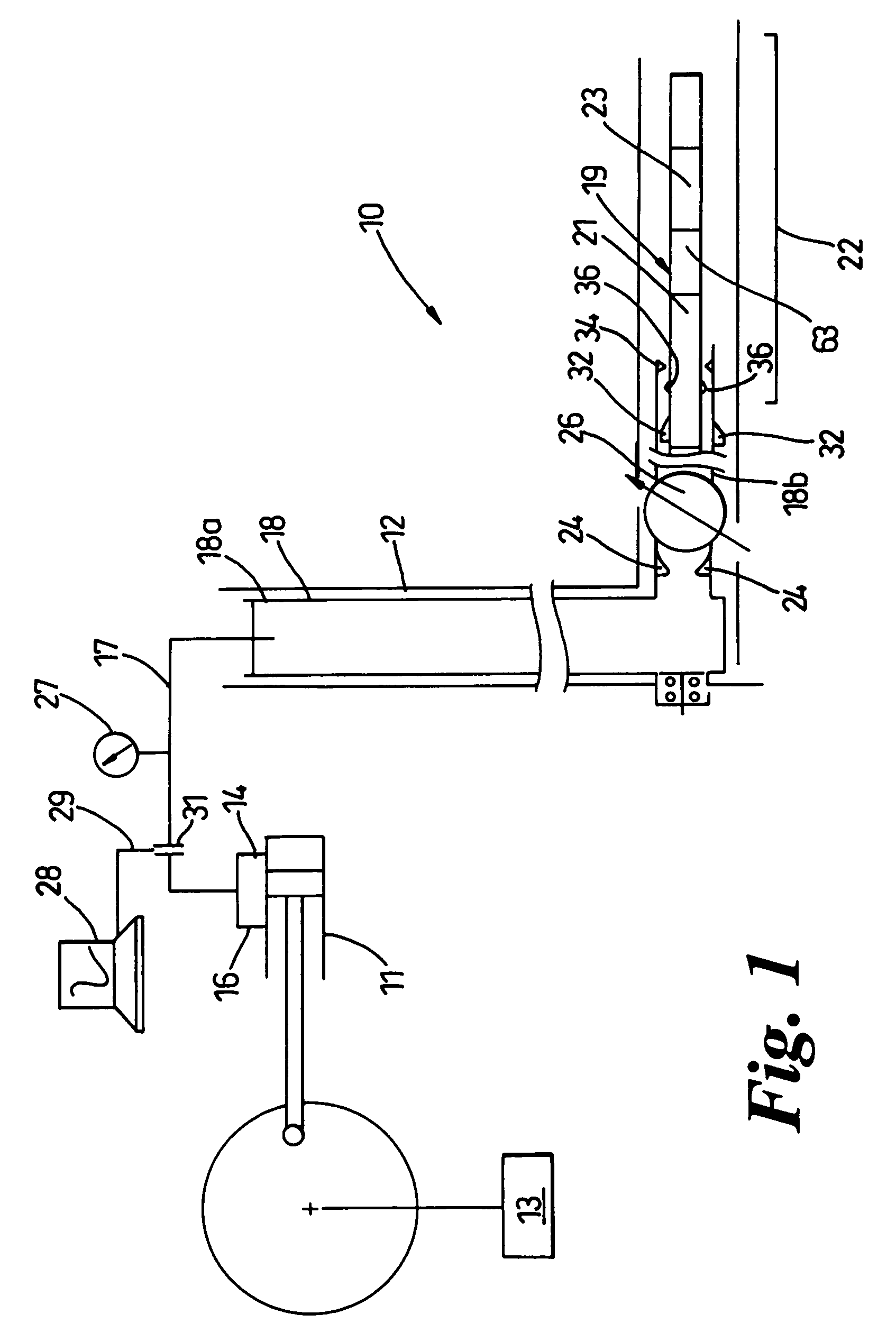
[0188]Referring to FIG. 1, apparatus 10 according to the invention includes a positive displacement pump 11 of a per se known kind for circulating fluid under pressure in a wellbore 12. A control device such as a microprocessor or other programmable device 13 controls the speed at which pump 11 pumps fluid in the wellbore 12.

[0189]Pump 11 is connected via appropriately valved connections 14, 16 in a per se known manner for circulating fluid in wellbore 12.

[0190]Programmable device 13 is in the embodiment of the invention shown capable of adjusting the output of pump 11 to provide a constant flow rate regardless of the fluid pressure in the wellbore 12. Techniques for achieving a constant flow rate pump output are known to those skilled in the relevant art.

[0191]The connections 14, 16 are connected as shown in FIG. 1 to a standpipe 17 that in the embodiment shown is at surface level, such that it is possible to gain physical access to the pressure in standpipe 17.

[0192]The end of sta...


PUM


Abstract

The apparatus includes a pump for circulating pressurized fluid in a wellbore. A control device controls the pump which a conduit interconnects to the wellbore. A downhole transducer detects changes in fluid pressure at a downhole location and generates signals accordingly. A processor generates actuator commands based on the signals. Actuators activate a downhole tool based on the actuator command. A modulating valve modulates the fluid pressure. A remote transducer detects the pressure remotely from the downhole transducer. The control device causes the pump to generate acoustic signals in the fluid via wave forms which the downhole transducer detects. The modulating valve generates wave forms in the fluid. The control device sends control signals via the fluid to the downhole transducer. Consequently the processor actuates the tools. Following correct actuation the modulating valve generates signals via pressure changes which the remote transducer receives to indicate successful tool deployment.

Description

CROSS-REFERENCE TO RELATED APPLICATIONS[0001]This application claims priority under 35 U.S.C. 119 to United Kingdom patent application 0218784.7 filed on Aug. 13, 2002.BACKGROUND OF THE INVENTION[0002]This invention relates to apparatuses and methods for deploying logging tools and signalling in boreholes.[0003]The logging of boreholes hitherto has used techniques that are well known in the oil and gas industries. The advantages of such an activity are known to those skilled in the art of oil and gas production.[0004]When a borehole is drilled, it is seldom smooth and regular. Sections of the borehole sometimes cave in. Sometimes there are other sections of rock, in particular shales and clays, that squeeze into the borehole as a result of pressure exerted by overlying strata.[0005]Traditionally, borehole logging has involved the use of a so-called wireline logging tool. The wireline logging tool is lowered on a wireline or pushed on drillpipe into the borehole to a downhole, loggin...

Claims


Application Information

Patent Timeline
IPC IPC(8): E21B44/00E21B28/00E21B43/12E21B23/04E21B47/18
CPCE21B47/18E21B47/20E21B47/24
Inventor CHAPLIN, MICHAEL JOHNEASTER, CHARLES RICHARDSPENCER, MICHAEL CHARLES
Owner REEVES WIRELINE TECH
Why Eureka
Try Eureka