Container for printing material and detector used for container
- Summary
- Abstract
- Description
- Claims
- Application Information
AI Technical Summary
Benefits of technology
Problems solved by technology
Method used
Image

Examples
Embodiment Construction
[0017]One mode of carrying out the invention is discussed below as a preferred embodiment in the following sequence:[0018]A. General Structure of Cartridge[0019]B. Electrical Structure of Cartridge[0020]C. Circuit Structure of Residual Ink Quantity Detector[0021]D. Ink Level Determination Routine[0022]E. Effects[0023]F. Modifications
[0024]A. General Structure of Cartridge
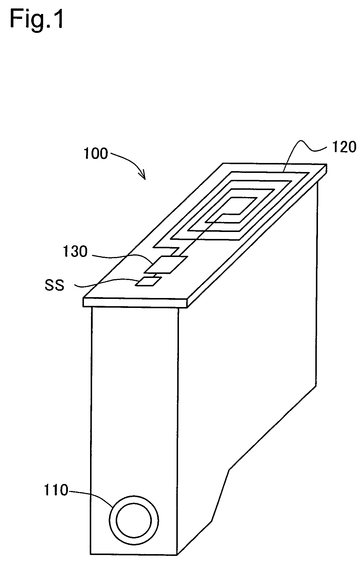
[0025]FIG. 1 is a perspective view illustrating the appearance of a cartridge 100 in one embodiment of the invention. An ink supply opening 110 is formed in the lower portion of the cartridge 100 to feed a supply of ink to a print head in a printer. The top face of the cartridge 100 has an antenna 120 for wireless communication with the printer, a sensor SS used to measure a residual quantity of ink, and a logic circuit 130.
[0026]In the structure of this embodiment, a piezoelectric element is used for the sensor SS. The cartridge 100 radiates an elastic wave, which is produced by vibrating the piezoelectric element ...
PUM
 Abstract
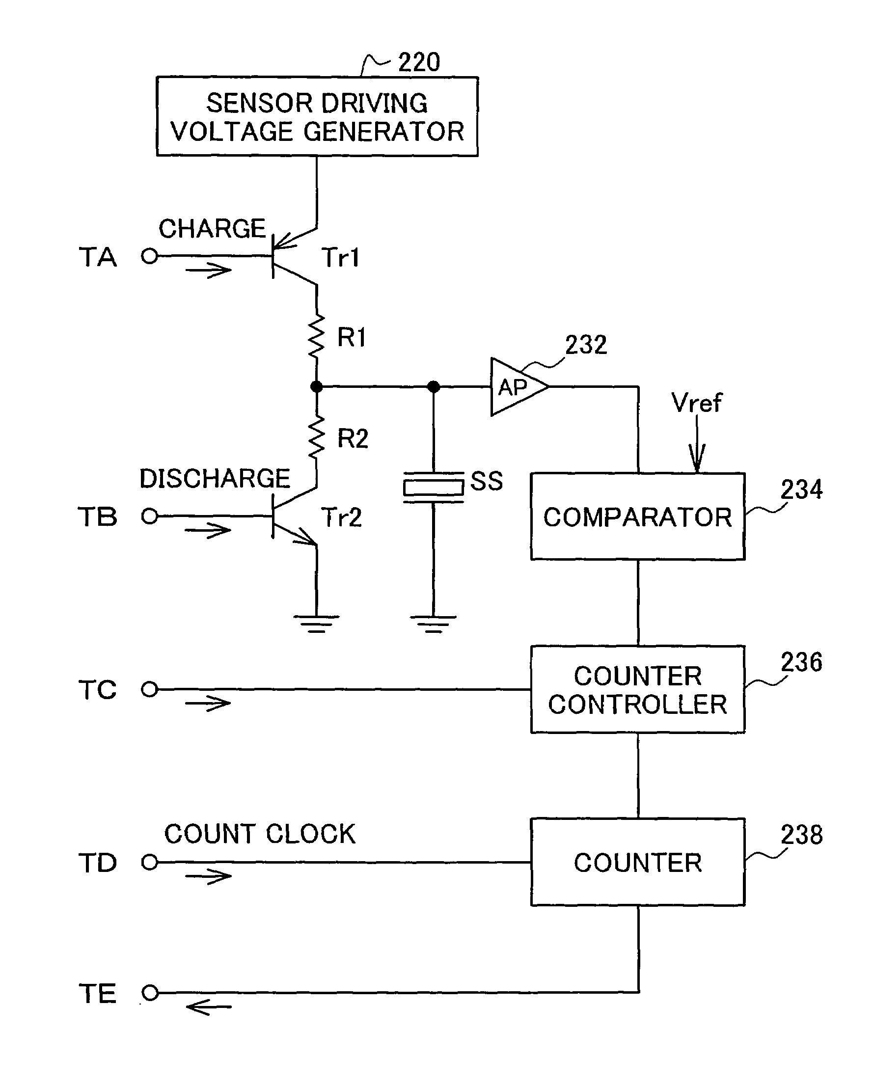
Description
Claims
Application Information
 - R&D
- Intellectual Property
- Life Sciences
- Materials
- Tech Scout
- Unparalleled Data Quality
- Higher Quality Content
- 60% Fewer Hallucinations
Browse by: Latest US Patents, China's latest patents, Technical Efficacy Thesaurus, Application Domain, Technology Topic, Popular Technical Reports.
© 2025 PatSnap. All rights reserved.Legal|Privacy policy|Modern Slavery Act Transparency Statement|Sitemap|About US| Contact US: help@patsnap.com