Everting balloon stent delivery system having tapered leading edge

a leading edge and stent technology, applied in the field of catheters for delivering medical devices, can solve the problems of increasing the initial friction between the sheath and the stent, and the stent that is longer may tend to generate greater friction

Inactive Publication Date: 2007-04-10
CARDINAL HEALTH SWITZERLAND 515 GMBH
View PDF32 Cites 136 Cited by
  • Summary
  • Abstract
  • Description
  • Claims
  • Application Information

AI Technical Summary

Problems solved by technology

With such an arrangement, there may be some amount of initial friction between the sheath and the stent th...

Method used


Image

  • Everting balloon stent delivery system having tapered leading edge
  • Everting balloon stent delivery system having tapered leading edge
  • Everting balloon stent delivery system having tapered leading edge

Examples


Embodiment Construction

[0033]The following description of the preferred embodiments of the present invention is merely illustrative in nature, and as such it does not limit in any way the present invention, its application, or uses. Numerous modifications may be made by those skilled in the art without departing from the true spirit and scope of the invention.

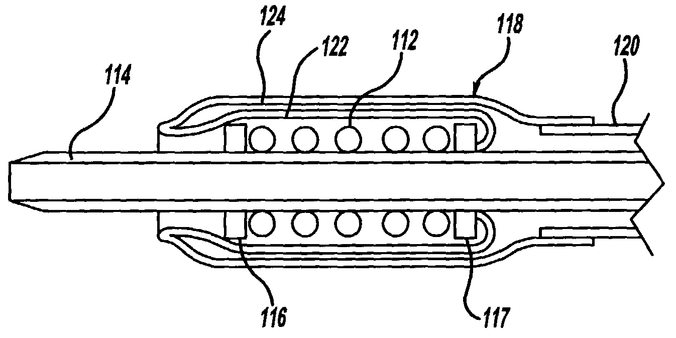
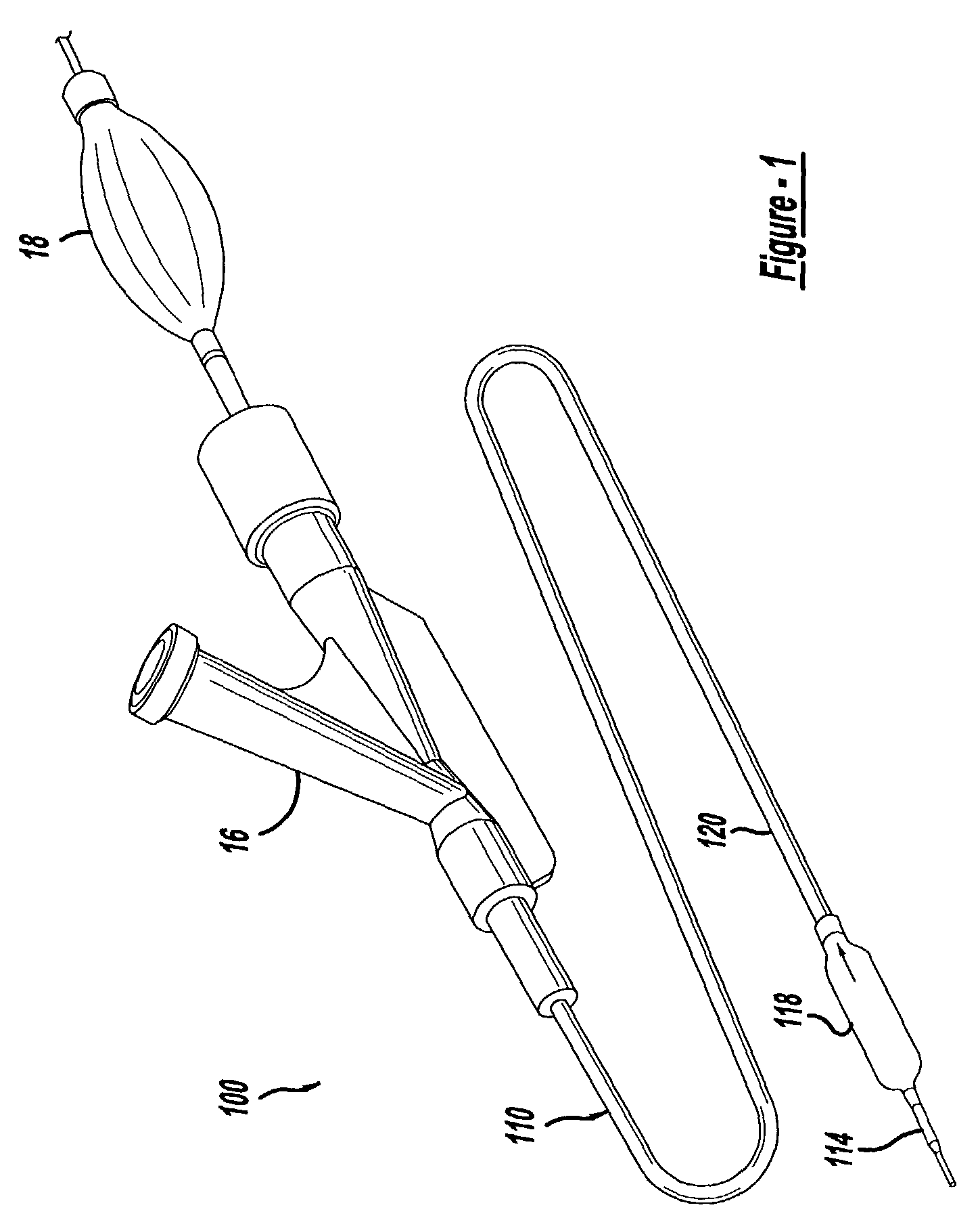
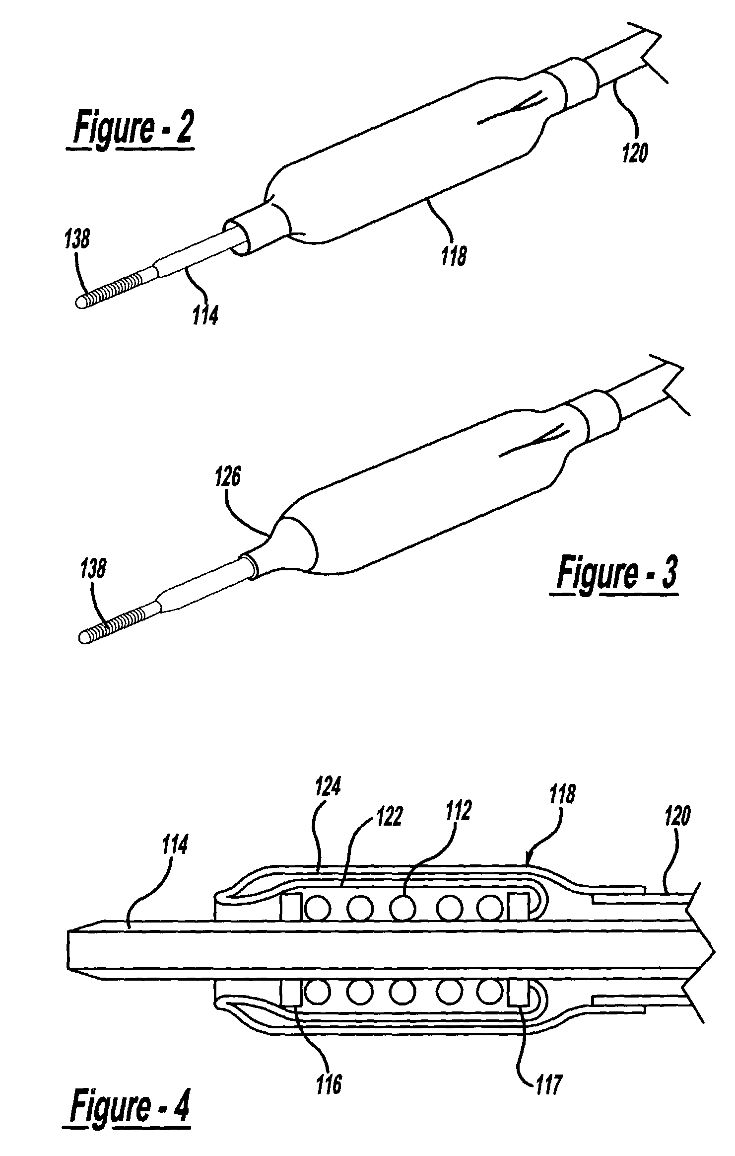
[0034]Referring to the drawings and to FIGS. 1 and 2 in particular, one embodiment of a catheter is shown generally at 10. The catheter 10 utilizes the usual guide wire 138. A flexible shaft inner body tube 114 surrounds the guide wire 138. In use, inner body 114 is slidable longitudinally on the guide wire for insertion into and withdrawal from a blood vessel or other body passage of a patient being treated.

[0035]An elongate cylindrical outer body tube 120 is concentrically disposed about the inner body 114. A proximal outer hub 16 is fixed to the proximal end of the outer body 120, and a proximal inner hub 18 is fixed to the proximal end of the inn...


PUM


Abstract

A stent delivery catheter includes at least an inner and outer body, and a specially shaped balloon affixed near one end of both of the inner and outer bodies. At least the outer body is tubular, and the space between the outer and inner bodies defines an inflation lumen for inflating and deflating the balloon. The balloon is designed to surround and hold a compressed self-expanding stent in a small initial size. An inner portion of the cylindrical balloon extends from where it is affixed to the inner body of the catheter shaft at a point proximal to the stent to a distal leading edge at a point distal to the stent. At this leading edge, the balloon is folded back upon itself, and an outer portion of the balloon extends proximally from the leading edge to a point proximal of the stent where it is affixed to the outer body of the catheter shaft. When the outer body is retracted in the proximal direction, the balloon progressively peels back or everts, to progressively release the stent. This peeling action minimizes any friction that may exist between the stent and balloon during stent deployment. The leading distal folded edge of the balloon, both inner and outer portions, are tapered inward. This inner and outer tapering of the balloon portions tends to protect the leading edge of the stent, provides for easier advancement of the catheter system along the desired body passageway for treatment, and minimizes friction as the balloon is retracted or peeled back upon itself.

Description

CROSS-REFERENCE TO RELATED APPLICATION[0001]The present invention is a continuation-in-part of U.S. patent application Ser. No. 09 / 532,353, filed on Mar. 21, 2000 now abandoned.BACKGROUND AND SUMMARY OF THE INVENTION[0002]1. Introduction[0003]This invention relates to medical devices, and more particularly to catheters for delivering medical devices.[0004]2. Discussion[0005]Stents are a type of medical device that has been used with great success to treat various conditions of patients, including narrowing or blockage of a blood vessel or other body passage. Generally, stents are often formed as cylindrical mesh tubes which expand from an initial configuration to a deployed shape. In the deployed shape, they act as scaffolding to hold open a body passage or lumen, such as an artery.[0006]Stents have so far been provided in two broad categories, balloon-expandable and self-expanding. Balloon-expandable stents are crimped around a deflated balloon of a balloon catheter, delivered to a...

Claims


Application Information

Patent Timeline
IPC IPC(8): A61F2/06A61F2/84
CPCA61F2/958A61F2002/9586
Inventor JOHNSON, KIRK L.QUERNS, LEGAL REPRESENTATIVE, MELISSAQUERNS, DECEASED, STEPHEN J.
Owner CARDINAL HEALTH SWITZERLAND 515 GMBH
Why Eureka
Try Eureka