Polarization maintaining optical fiber coupler and method of manufacturing same

a technology of polarization maintaining optical fiber and coupler, which is applied in the direction of manufacturing tools, cladded optical fibre, instruments, etc., can solve the problems of wavelength dependence, easy generation of excess loss, and excess loss

Inactive Publication Date: 2007-04-10
THE FUJIKURA CABLE WORKS LTD
View PDF14 Cites 18 Cited by
  • Summary
  • Abstract
  • Description
  • Claims
  • Application Information

AI Technical Summary

Benefits of technology

[0022]The polarization maintaining optical fiber coupler having the structure described above can also be a polarization maintaining wavelength division multiplex coupler.
[0023]In the polarization maintaining optical fiber coupler having the structure described above, it is preferable that the polarization maintaining optical fiber is a PANDA type optical fiber.
[0024]In the polarization maintaining optical fiber coupler having the structure described above, it is preferable that the polarization maintaining optical fiber is a Bow-Tie type optical fiber.
[0025]According to another aspect of the present invention, there is provided a method of manufacturing a polarization maintaining optical fiber coupler including a plurality of polarization maintaining optical fibers, each having a core, cladding surrounding the core, and two stress applying portions within the cladding that are arranged symmetrically around the core, the plurality of polarization maintaining optical fibers being arranged parallel to each other and having a portion in a longitudinal direction thereof fused and extended so as to form a fused and extended portion, including: removing an outer peripheral portion of the cladding in a portion in a longitudinal direction of at least one of the polarization maintaining optical fibers to narrow a diameter of the at least one of the polarization maintaining optical fibers without exposing the stress applying portions; and fusing and extending the narrowed portion to form the fused and extended portion.
[0026]In the method of manufacturing a polarization maintaining optical fiber coupler having the structure described above, it is preferable that the distance between adjacent outer circumferences of the two stress applying portions is 20 μm or more in the polarization maintaining optical fibers.
[0027]In the method of manufacturing a polarization maintaining optical fiber coupler having the structure described above, it is preferable that a length of the narrowed portion of the polarization maintaining optical fiber is 40 mm or less.

Problems solved by technology

Polarization maintaining optical fiber couplers manufactured by the fusion and extension of polarization maintaining optical fibers, as is described above, have a problem because excess loss tends to be generated in the fused and extended portion (i.e., loss generated in the fused and extended portion) by the manufacturing process.
The problem of excess loss being easily generated is not limited to polarization maintaining optical fiber couplers that use PANDA type optical fibers, but is also generated in the same manner in polarization maintaining optical fiber couplers that use other polarization maintaining optical fibers such as Bow-Tie type optical fibers and the like.
However, if excess loss increases temporarily during the fusion and extension of a polarization maintaining optical fiber, wavelength dependency of the excess loss of the polarization maintaining optical fiber coupler also increases and it becomes difficult for the polarization maintaining optical fiber coupler to be used in applications having a broad used bandwidth.
Moreover, the task of adjusting manufacturing conditions such that excess loss is at a minimum in order to obtain the desired coupling characteristics is a barrier to improving productivity.

Method used


Image

  • Polarization maintaining optical fiber coupler and method of manufacturing same
  • Polarization maintaining optical fiber coupler and method of manufacturing same
  • Polarization maintaining optical fiber coupler and method of manufacturing same

Examples


example 1

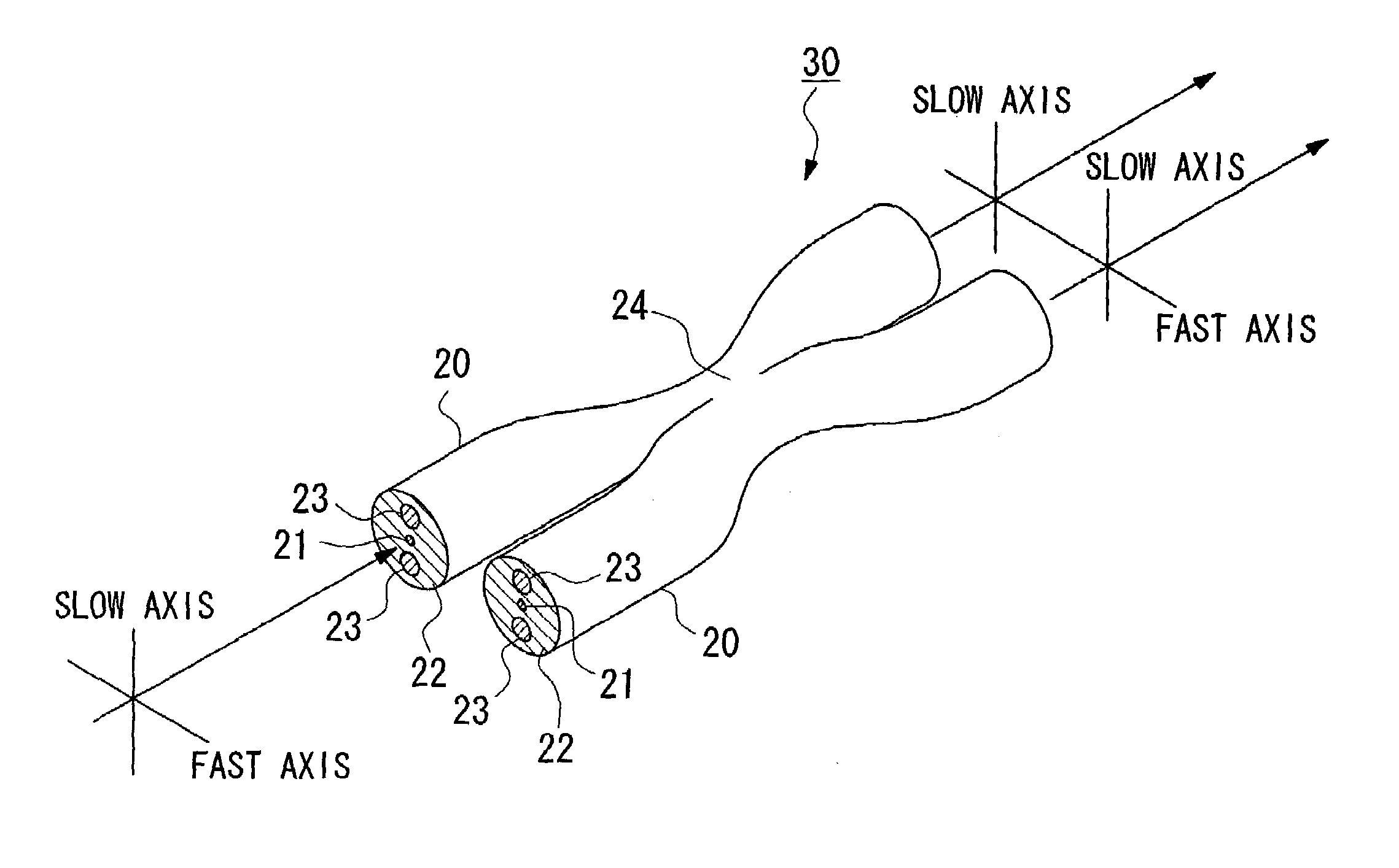
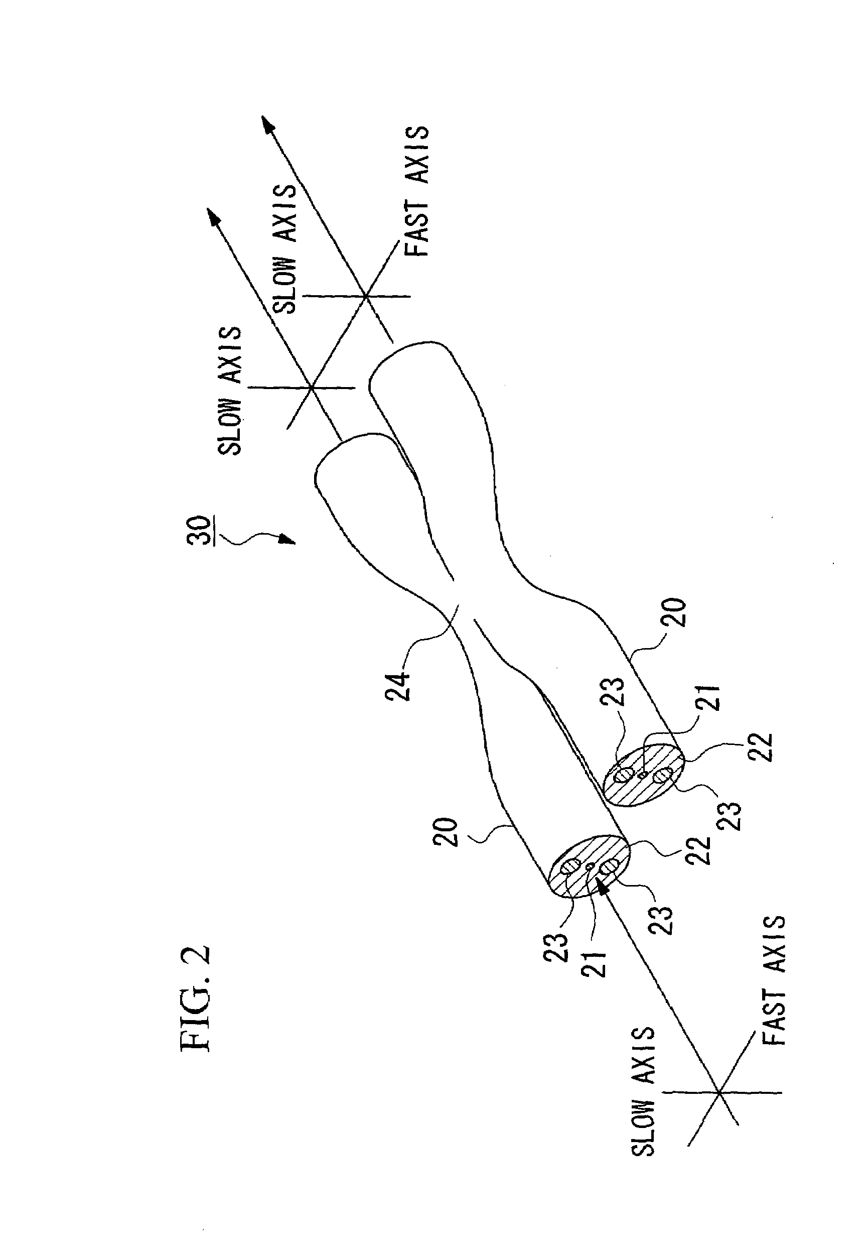
[0077]A PANDA type optical fiber having an outer diameter of approximately 125 μm underwent diameter narrowing processing via an etching method or the like that used hydrofluoric acid. As a result, a PANDA type optical fiber 20, such as that shown in FIG. 5A, was obtained. The outer diameter of this PANDA optical fiber 20 was approximately 95 μm. The outer diameters of two stress applying portions 23 was approximately 36 μm. The distance between adjacent outer circumferences of the two stress applying portions 23 on an axis connecting the centers of the two stress applying portions 23 was approximately 19 μm. The thickness of the cladding 22 on the outer side of the two stress applying portions 23 on an axis connecting the centers of the two stress applying portions 23 was approximately 2 μm.

[0078]According to necessity, a portion of a covering layer formed by plastic or the like provided on the surfaces of two of these PANDA optical fibers 20 was removed. Next, the two PANDA optica...

example 2

[0087]A PANDA type optical fiber having an outer diameter of approximately 125 μm underwent diameter narrowing processing via an etching method or the like that used hydrofluoric acid. As a result, a PANDA type optical fiber 20, such as that shown in FIG. 9A, was obtained. The outer diameter of this PANDA optical fiber 20 was approximately 105 μm. The outer diameters of two stress applying portions 23 were approximately 36 μm. The distance between adjacent outer circumferences of the two stress applying portions 23 on an axis connecting the centers of the two stress applying portions 23 was approximately 30 μm. The thickness of the cladding 22 on the outer side of the two stress applying portions 23 on an axis connecting the centers of the two stress applying portions 23 was approximately 2 μm.

[0088]According to necessity, a portion of a covering layer formed by plastic or the like provided on the surfaces of two of these PANDA optical fibers 20 was removed. Next, the two PANDA opti...

example 3

[0098]A PANDA type optical fiber having an outer diameter of approximately 125 μm underwent diameter narrowing processing via an etching method or the like that used hydrofluoric acid. As a result, a PANDA type optical fiber 20, such as that shown in FIG. 9A, was obtained. The outer diameter of this PANDA optical fiber 20 was approximately 105 μm. The outer diameters of two stress applying portions 23 was approximately 36 μm. The distance between adjacent outer circumferences of the two stress applying portions 23 on an axis connecting the centers of the two stress applying portions 23 was approximately 30 μm. The thickness of the cladding 22 on the outer side of the two stress applying portions 23 on an axis connecting the centers of the two stress applying portions 23 was approximately 2 μm.

[0099]According to necessity, a portion of a covering layer formed by plastic or the like provided on the surfaces of two of these PANDA optical fibers 20 was removed. Next, the two PANDA optic...


PUM

PropertyMeasurementUnit
thicknessaaaaaaaaaa
thicknessaaaaaaaaaa
distanceaaaaaaaaaa

Abstract

There is provided a polarization maintaining optical fiber coupler and a method of manufacturing this polarization maintaining optical fiber coupler in which manufacturing is simplified and excess loss is reduced. A polarization maintaining optical fiber coupler is provided in which, in at least one of the polarization maintaining optical fibers forming the fused and extended portion, the ratio of the [diameter of the core/the diameter of the cladding] or [the distance between the two stress applying portions/the diameter of the cladding] is greater than the ration of the [diameter of the core/the diameter of the cladding] or [the distance between the two stress applying portions/the diameter of the cladding in the portions of the polarization maintaining optical fibers that do not form the fused and extended portion]. In addition, in this polarization maintaining optical fiber coupler, in the fused and extended portion, the stress applying portions are enveloped by the cladding. Moreover, polarization maintaining optical fibers are used in which the distance between adjacent outer circumferences of the two stress applying portions is 20 μm or more.

Description

BACKGROUND OF THE INVENTION[0001]Priorities are claimed under 35 U.S.C. § 119 to Japanese Patent Applications Nos. 2002-234981 filed Aug. 12, 2002 and 2003-199269 filed Jul. 18, 2003, which are incorporated herein by reference.[0002]1. Field of the Invention[0003]The present invention relates to a polarization maintaining optical fiber coupler and, in particular, to a polarization maintaining optical fiber coupler that reduces loss generated in a fusion and extension process of a fused and extended portion.[0004]2. Description of the Related Art[0005]Various types of polarization maintaining optical fiber couplers have been proposed, and the polarization maintaining and absorption reducing (PANDA) type optical fiber is typical.[0006]FIG. 18 is a cross-sectional view showing an example of a PANDA type optical fiber. This PANDA type optical fiber 10 is formed with a core 11 provided in the center of the optical fiber 10, cladding 12 that is provided in the shape of a concentric circle...

Claims


Application Information

Patent Timeline
Patent Type & Authority Patents(United States)
IPC IPC(8): G02B6/26C03B37/023G02B6/02G02B6/42G02B6/287G02B6/28
CPCG02B6/2835G02B6/2843G02B2006/2839
Inventor OUCHI, YASUHIROTANAKA, DAIICHIRO
Owner THE FUJIKURA CABLE WORKS LTD
Why Eureka
Try Eureka