Shaped spectral coding and recording systems therefor

a spectral coding and shape technology, applied in the field of encoding techniques, can solve the problems of entanglement of certain loss of energy and limited reaction time, and achieve the effect of simple decoding methods and higher encoding ratios

Inactive Publication Date: 2007-04-10
STMICROELECTRONICS SRL
View PDF4 Cites 5 Cited by
  • Summary
  • Abstract
  • Description
  • Claims
  • Application Information

AI Technical Summary

Benefits of technology

[0010]The object of the present invention is to provide a further enhanced solution with respect to the previously indicated solutions, especially regarding the possibility of obtaining higher encoding ratios and achieving simpler decoding methods.

Problems solved by technology

Since, for various reasons, the stages of the read chain are mutually AC-coupled, a certain loss of energy is entailed, which is more noticeable than that occurring in “longitudinal” magnetic recording systems.
Nevertheless, the system is expected to be capable of tracking constant non-zero levels over an indefinite period of time; this is clearly impossible, since even a low AC-coupling gives rise to an appreciable reaction after more than a hundred samples: this phenomenon is known in the art as the Base Line Wander, or BLW for short.
The corresponding reaction time is limited, however, due to both the latencies intrinsic in the implementation and the need to realize a decoupling from the control loops, such as those that perform control of the gain, equalisation and sample timing functions.

Method used


Image

  • Shaped spectral coding and recording systems therefor
  • Shaped spectral coding and recording systems therefor
  • Shaped spectral coding and recording systems therefor

Examples


Embodiment Construction

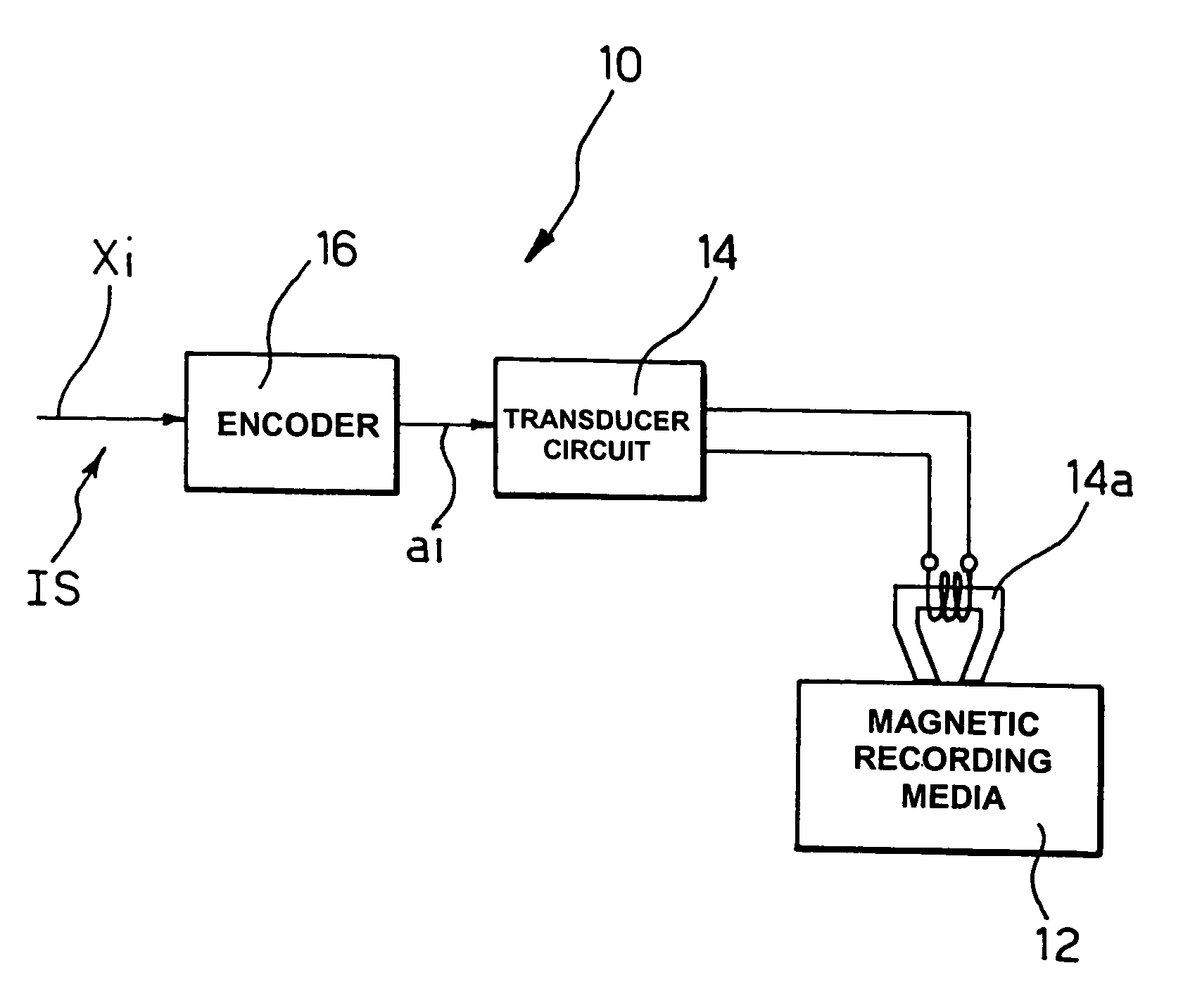
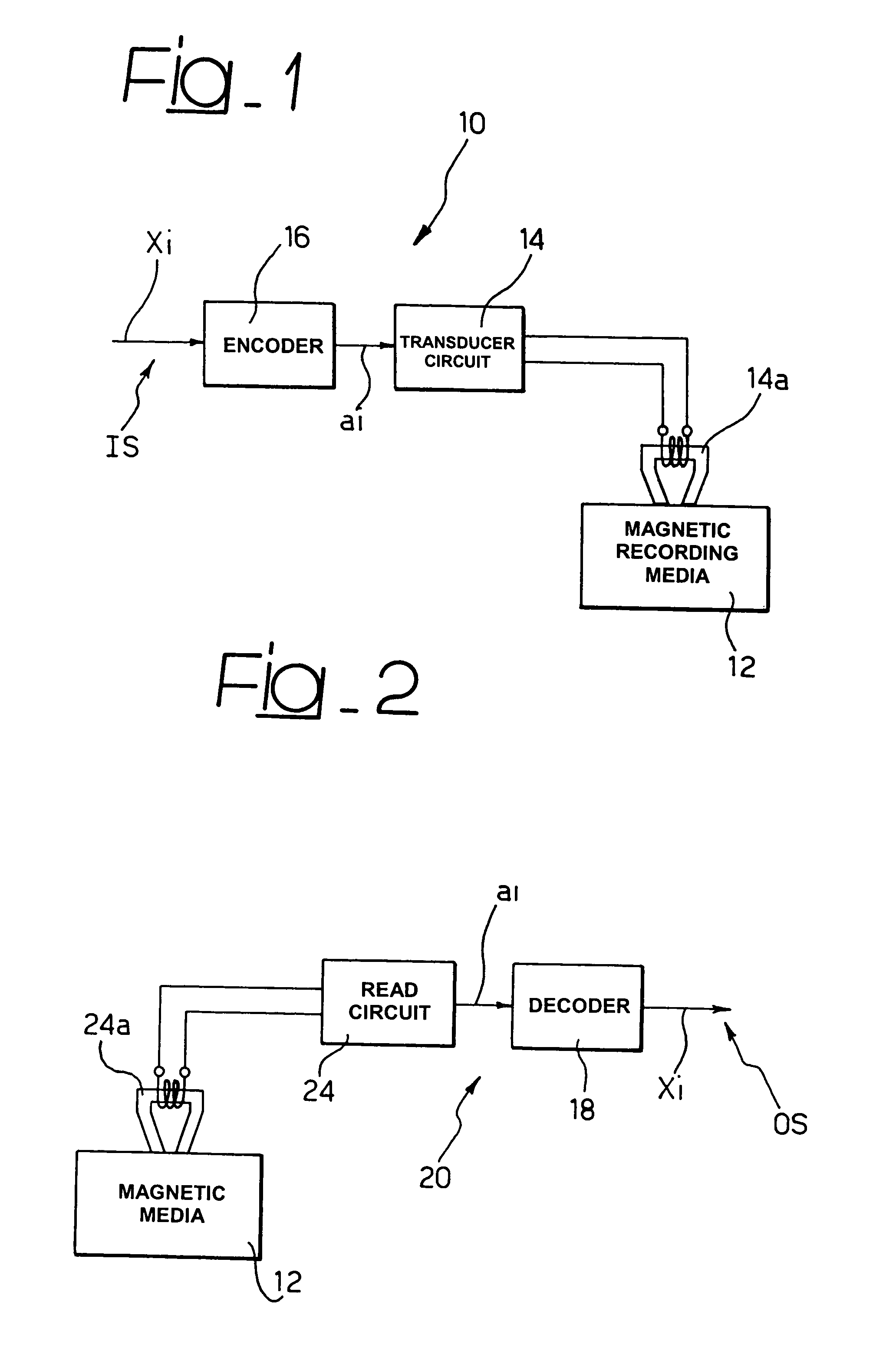
[0017]FIG. 1 illustrates the general layout of a system, indicated as a whole by reference 10, for recording a digital input signal stream, indicated as IS, onto a known type of magnetic recording media 12 using a vertical magnetic recording technique.

[0018]Recording media of this type are well known in the art, as applied to hard disks used in personal computers for example.

[0019]This also holds for the transducer circuit, indicated as 14, that, via a magnetic write head indicated as 14a, allows encoded digital signals, the symbols of which are generally indicated as ai, to be written onto the media 12.

[0020]The symbols ai are obtained via the MSN encoding technique, described further on, in the form of code blocks generated by an encoder 16 from a sequence of input symbols, indicated as xi.

[0021]In a similar manner, the block diagram in FIG. 2 shows a system, indicated in its entirety as reference 20, possessing the complementary function, or rather that of reading magnetic media ...


PUM

PropertyMeasurementUnit
lengthaaaaaaaaaa
trellis structureaaaaaaaaaa
storage densityaaaaaaaaaa

Abstract

In the MSN encoded form, the symbols of each block of the present invention define a running digital sum (RDS) value, defined as RDS([a0a1 . . . aN−1])=−Σi(−1)ai where the symbols ai belong to the set {0, 1} and the sum extends for values of i from 0 to N−1. An encoder is configured to satisfy at least one of the following characteristics: a) blocks of symbols with a given length (L) are used for encoding, wherein RDS=RDS0+4.K, where K is an integer, RDS is the said running digital sum, RDS0 is defined as zero for even values of the said length (L), and one for odd values of said length (L), and b) blocks of symbols with a given length (L) are used for MSN coding and encoding is effected by selecting encoded blocks such that the set of running digital sum (RDS) values is the set with the minimum number of elements that satisfy the required rate value, defined as the ratio between the length of the input blocks and the length of the output blocks. A decoder with a simplified trellis structure is used for decoding (as in decoding a digital signal read from media on which the signal in question has been recorded via a vertical or perpendicular magnetic recording technique, for example).

Description

FIELD OF THE INVENTION[0001]The present invention relates to encoding techniques and has been developed with particular attention to possible application in magnetic recording techniques of the “vertical” or “perpendicular” type.BACKGROUND OF THE INVENTION[0002]The aforesaid recording techniques are considered to be particularly interesting from the viewpoint of achieving improvements in storage density with respect to current storage techniques, substantially based on a “longitudinal” utilization of the recording media.[0003]As opposed to “longitudinal” recording techniques, the waveform read in “vertical” recording systems exhibits a significant energy level even at very low frequencies.[0004]Since, for various reasons, the stages of the read chain are mutually AC-coupled, a certain loss of energy is entailed, which is more noticeable than that occurring in “longitudinal” magnetic recording systems.[0005]To limit this drawback, the AC-coupling frequency is normally kept below 1% o...

Claims


Application Information

Patent Timeline
Patent Type & Authority Patents(United States)
IPC IPC(8): H03M13/00G11B5/00G11B5/09G11B20/10G11B20/14G11B20/18H03M5/14H03M7/46H03M13/25H03M13/31H03M13/41
CPCG11B5/09G11B20/10009G11B20/10055G11B20/1426G11B20/1803H03M5/145H03M7/46H03M13/31H03M13/41H03M13/6312H03M13/6343G11B2005/0029
Inventor DATI, ANGELOROSSI, AUGUSTOGIOVENZANA, DAVIDE
Owner STMICROELECTRONICS SRL
Why Eureka
Try Eureka