Roofing shingle with headlap seal and improved coverage

a technology of roof shingle and seal, which is applied in the field of roof shingle, can solve the problems of leaking onto the roof deck, shingle tab, and underlying shingles having built-in weakness, so as to reduce the width of the shingle of the invention, prevent bleeding over the edge, and reduce the lifting of tabs

Active Publication Date: 2007-04-17
BUILDING PROD OF CANADA CORP
View PDF15 Cites 71 Cited by
  • Summary
  • Abstract
  • Description
  • Claims
  • Application Information

AI Technical Summary

Benefits of technology

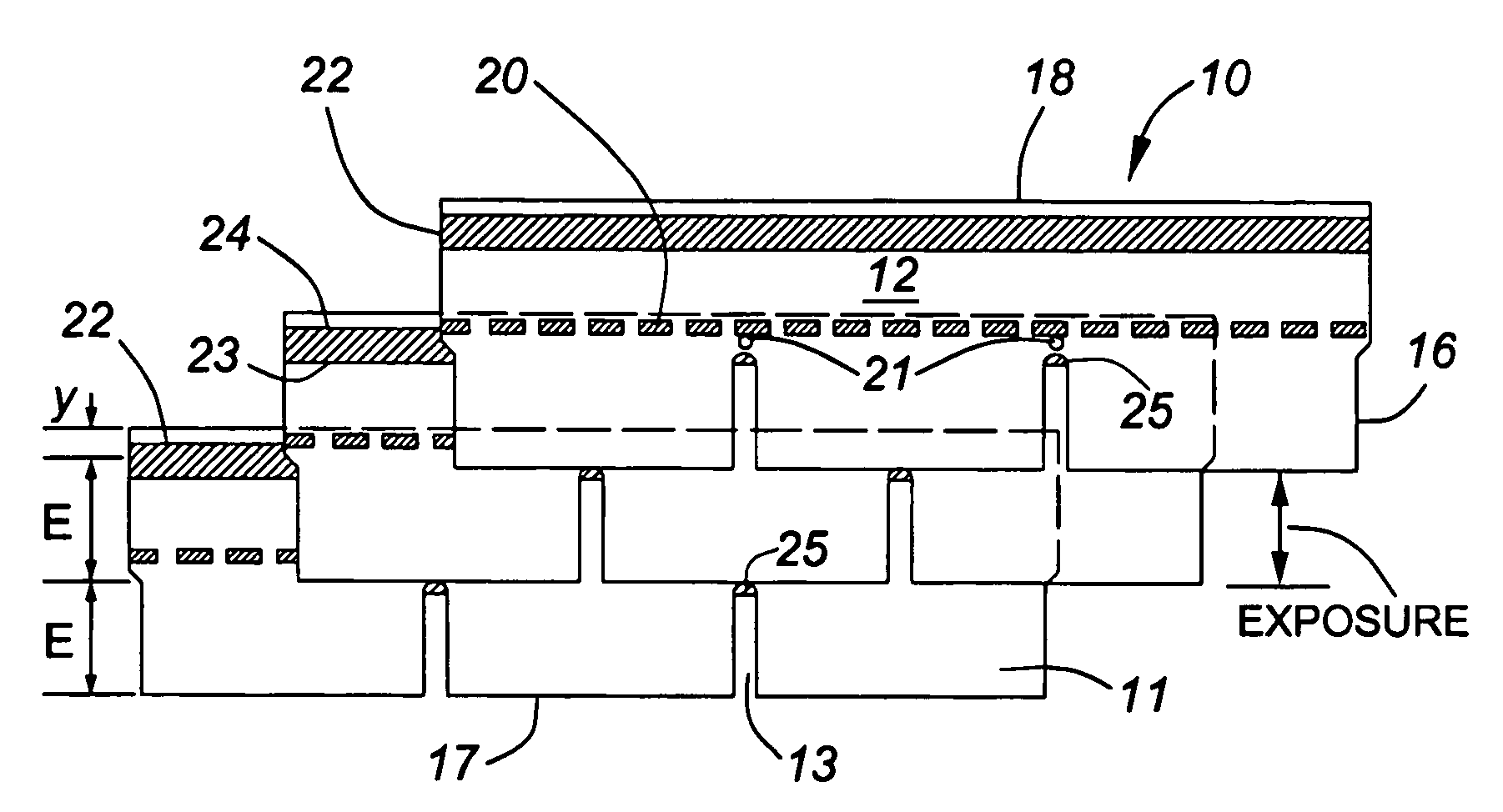
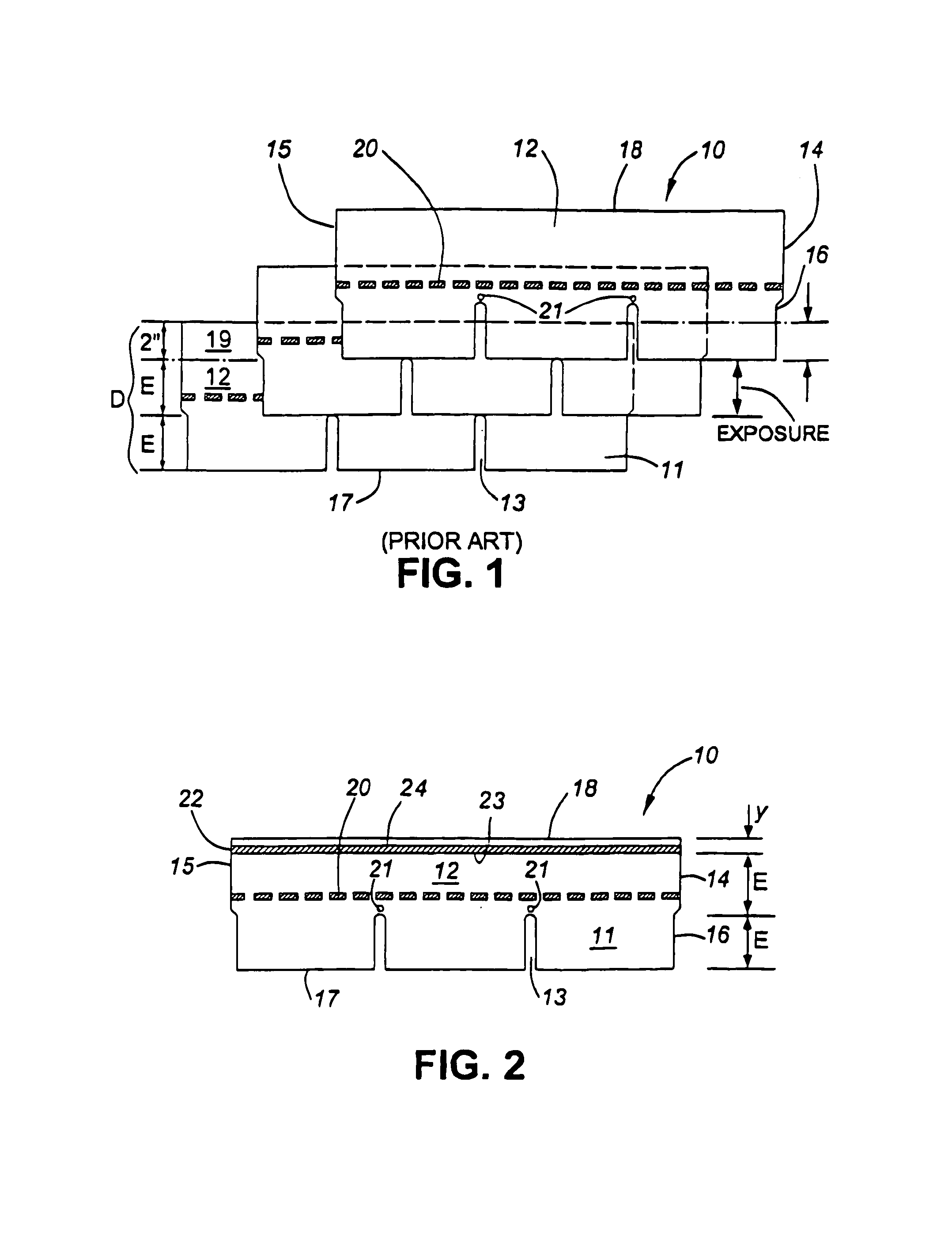
[0020]From the foregoing perspective, the present invention addresses the substantial elimination of moisture penetration under the shingles and onto the roof deck by providing a continuous sealant barrier near the top or head edge of each shingle. This sealant barrier, which operates in conjunction with the typical stitched adhesive strip, creates a stiffer, more integral roofing shingle system, thereby reducing the lifting of tabs and the consequent entry of moisture through the first stitched adhesive strip. The sealant barrier of the invention is continuous, thereby preventing water from reaching the head edge of the shingles, even excluding moisture which may enter at the cut-out of a tabbed shingle.
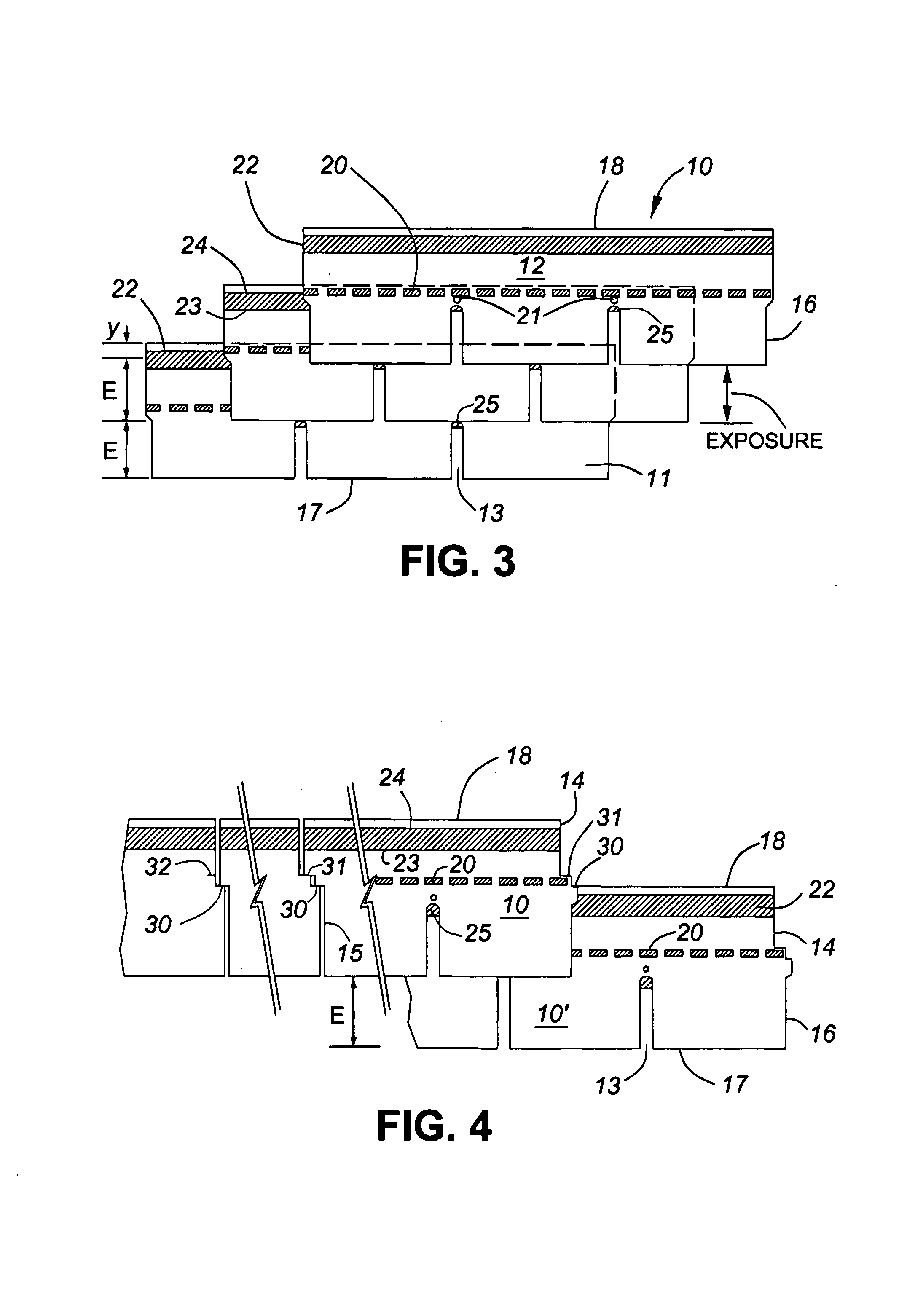
[0021]In one aspect of the present invention, a monoplanar roofing shingle, (having a generally uniform thickness) with a tab or flap portion and main body portion, has a conventional stitched or intermittent adhesive strip located just above the line of the apices or top ends of the cut-outs between the tabs. That adhesive strip adheres the tabs of an overlying shingle. More importantly, a continuous sealant strip is applied to the shingle surface near the top or head edge, but spaced sufficiently therefrom to prevent bleeding over the edge. The precise position of the second adhesive strip is important to the full attainment of a barrier seal. In the shingle of the present invention, the second sealant strip is positioned above (towards the head or top edge of the shingle) a hypothetical line located above the exposure of the shingle by an amount equal to the width of the exposure. In the parlance of the industry, the sealant strip would be 2× exposure from the butt edge of the shingle. In a preferred embodiment of the invention, the lower edge of the second sealant strip extends below the hypothetical line whereby the apex of the cut-out of an overlying shingle is sealed within the second sealant strip. In a tabbed shingle, the second sealant strip is similarly located above the butt edge a distance equal to 2× the “exposure”, or cut-out length.
[0022]A further aspect of the invention is that the width of the shingle of the invention may be reduced, or the coverage of the shingle increased, relative to a traditional shingle having a width of 2× exposure+2″.
[0023]In still a further aspect of the shingle of the present invention, a novel side gauging notch permits the shingles to be selectively installed with a traditional 2″ headlap, or alternatively to utilize the advantageous extended coverage aspect of the present invention.

Problems solved by technology

Current shingles have a built-in weakness, namely the shingle tab adhesive compound is applied in a “stitch” or intermittent pattern (as opposed to a continuous strip of adhesive along the length of the shingle).
If rain is driven under the overlying shingles or through the stitch gaps and penetrates between the shingles sufficiently to exceed the “headlap”, it overflows the top or head edge of the underlying shingles and spills onto the roof deck.
When shingle damage is done, rainwater can easily damage the wooden deck and subsequently the interior of the building.
Consequently, the traditional 2″ headlap is unnecessary.

Method used


Image

  • Roofing shingle with headlap seal and improved coverage
  • Roofing shingle with headlap seal and improved coverage
  • Roofing shingle with headlap seal and improved coverage

Examples


example 1

[0038]In the United States and Canada, wind and rain penetration has been the subject matter of numerous building codes. Dade County, in Florida, and the Canadian Construction Materials Centre have established the highest standards, requiring that shingles withstand wind and rain penetration to 110 mph (175 kph). Other organizations, such as ASTM and CSA, merely require that shingles resist wind uplift (stitch failure) up to 60 mph (90 kph).

[0039]In dynamic tests conducted by the applicant, conventional three tab shingles installed conventionally, (5⅝″ exposure with 2″ headlap) with only the tab stitch adhesive, passed the standard ASTM / CSA wind uplift test as no tabs failed under winds of 60 mph (90 kph). Nonetheless, the same three tab shingles experienced rain penetration under a wind and rain loading of 50 mph (80 kph). Only an underlayment would have retarded consequent water damage.

[0040]In contrast, dynamic tests of shingles of the present invention, with increased exposure (...

example 2

[0042]For a shingle having a 5″ exposure (E) by a 36″ length, in order to cover 100 square feet of roof, 80 shingles would be required.

i.e.100÷(5″×36″ / 144)=80

[0043]However, in the present invention, with a sealant band and reduced headlap, the same shingle could increase exposure to 5½″. The number of shingles required to cover 100 square feet of roof would be approximately 73,

i.e. 100÷(5.5″×36″ / 144)=72.73.

[0044]This approach allows the same coverage of roof with some seven fewer shingles (approximately 10%). Conversely, one could choose not to increase the exposure of the shingles, but could reduce the width of the shingle by the same amount of 1″ which would also allow a reduction in raw material consumption. With increased coverage, fewer shingles need be applied and both time and labour costs are reduced. Consequently, there is a clear economic benefit for the manufacturer, roofing applicators (contractors), and ultimately consumers (home owners). This economic benefit is additi...


PUM


Abstract

A roofing shingle for enhanced wind/rain durability embodies two transverse lines of adhesion. A first discontinuous line of adhesive joins the butt edge of an overlying shingle to the underlying shingle. Secondly, a band of sealant adjacent the top edge of an underlying shingle seals against an overlying shingle to prevent penetration by wind driven rain to the roof deck. A reduced headlap is thereby permitted, thereby either reducing shingle size or extending shingle coverage. Exposed portions of the sealant band improve the erosion resistance of underlying shingles.

Description

FIELD OF THE INVENTION[0001]The present invention relates to the art of roofing shingles and in particular to roofing shingles that must withstand exposure to high winds and driving rain as well as pooling water arising from ice damming. This invention relates generally to an improved roofing shingle and its use in a roofing system which exhibits superior resistance to wind driven rain. The shingle of the present invention embodies adhesive sealant elements located in specific areas to achieve a more unified, integral roof shingle system adapted to substantially withstand and shed wind driven rain. A corollary benefit of the present invention is the ability to reduce the standard requirement of a two inch headlap, resulting in substantially greater coverage for the same shingle quantities and lower labour costs, all without degrading the structural integrity and performance of the roofing shingle system.BACKGROUND OF THE INVENTION[0002]Traditional granular surfaced roofing shingles ...

Claims


Application Information

Patent Timeline
Patent Type & Authority Patents(United States)
IPC IPC(8): E04D1/26E04D1/34
CPCE04D1/26E04D1/34E04D2001/3435Y10T428/24372E04D2001/3485E04D2001/3491E04D2001/3447E04D1/2918E04D1/29
Inventor KANDALGAONKAR, JAYANT B.
Owner BUILDING PROD OF CANADA CORP
Why Eureka
Try Eureka