
Overload coupling

a technology of overload coupling and drive assembly, which is applied in the direction of couplings, mechanical equipment, understructures, etc., can solve the problems of load peak, damage, failure of gearing, etc., and achieve the effect of increasing the service life of the drive assembly

Inactive Publication Date: 2007-04-17
BRP ROTAX
View PDF12 Cites 26 Cited by
  • Summary
  • Abstract
  • Description
  • Claims
  • Application Information

AI Technical Summary

Benefits of technology

[0008]It is therefore one aspect of one or more embodiments of this invention to provide an overload clutch that is smaller, more durable, and / or less expensive than conventional overload clutches.
[0010]It is another aspect of embodiments of the present invention to create a drive assembly of the type described heretofore for a motor vehicle where excessive load peaks in the drive train can be avoided without having to abandon the proven drive concept. It is also to be possible to avoid peak loads of this kind by retrofitting existing drive trains.
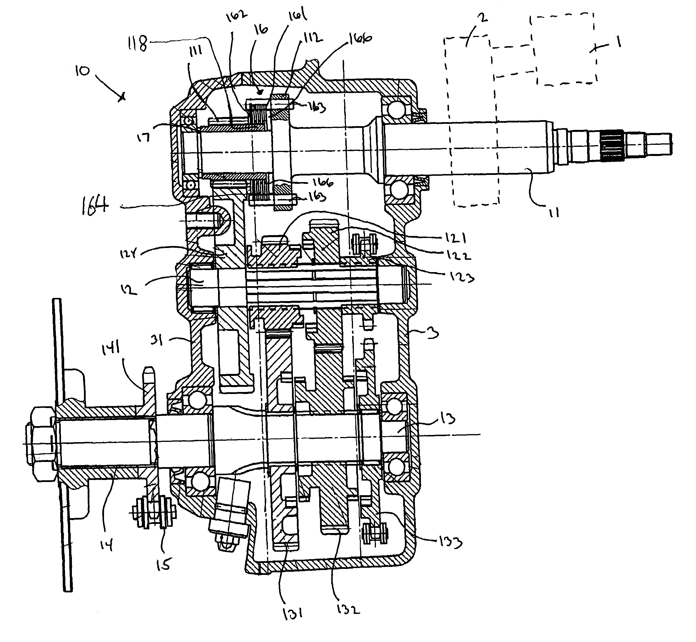
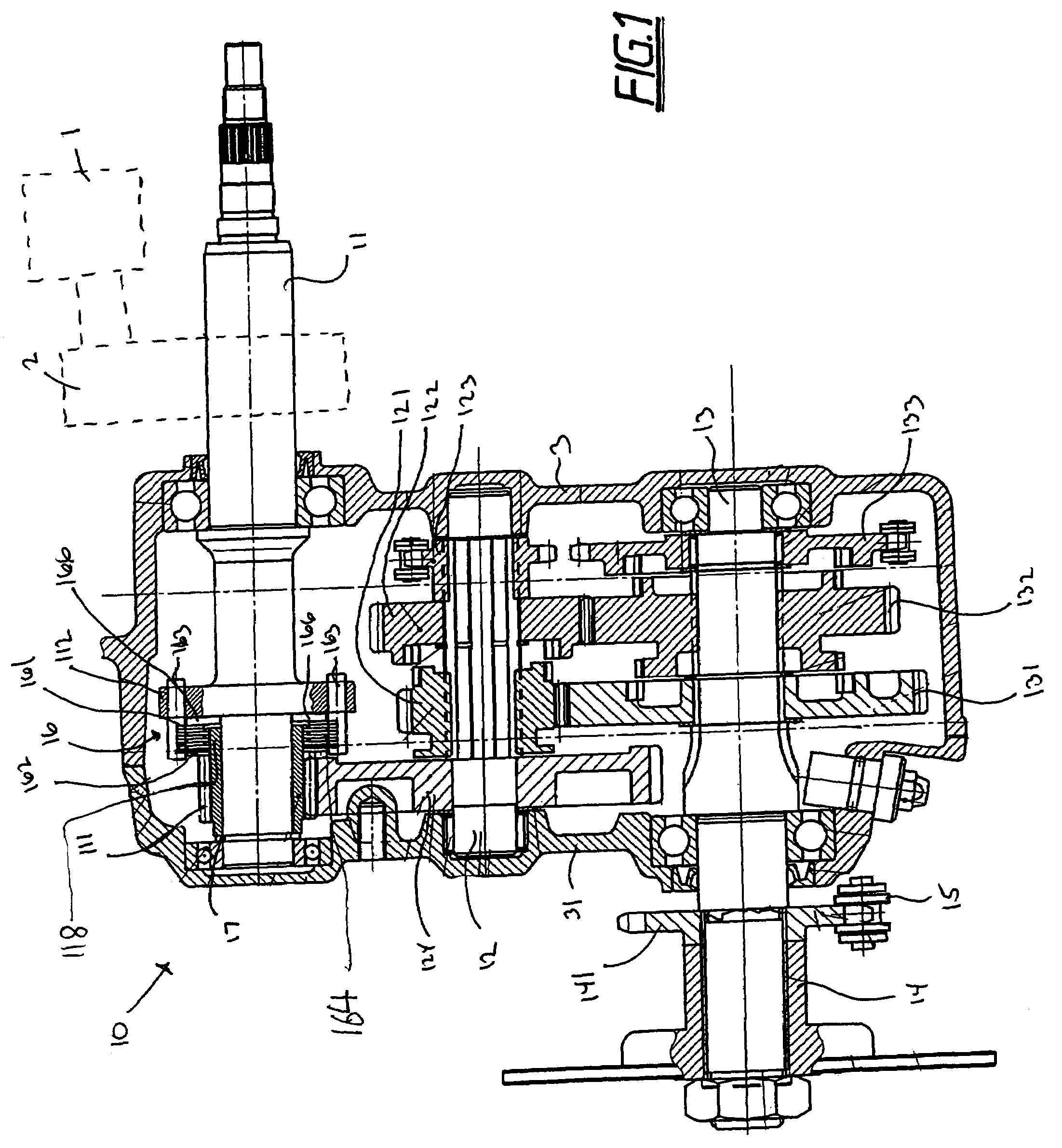
[0011]This objective is achieved by embodiments of the present invention whereby an overload clutch is included as part of the drive assembly. This solves the problem by suppressing excessive torques and load peaks in the drive assembly in a particularly simple and elegant manner without any negative effects on the normal operation of the drive assembly. The design of the overload clutch is such that it can transfer the maximal engine torque and any minor shock loads that may occur reliably. The arrangement only reduces excessive shocks whereby it releases the connection between the CVT and the drive shaft of the wheels (i.e., the output shaft)—which is rigid during normal operation—for brief periods so as to reduce the load peaks.
[0012]Depending on the amount of space that may be available, the overload clutch is installed in the drive assembly between the input shaft and the output shaft of the drive assembly. It is particularly advantageous if the overload clutch is arranged on the input shaft because the output torque that is to be limited to a maximum value on the output shaft can be reduced by the transmission ratio of the drive assembly so that the torque that is to be limited in the drive train is also reduced by this transmission ratio, which means that the overload clutch can be made smaller. This in turn also reduces production costs.
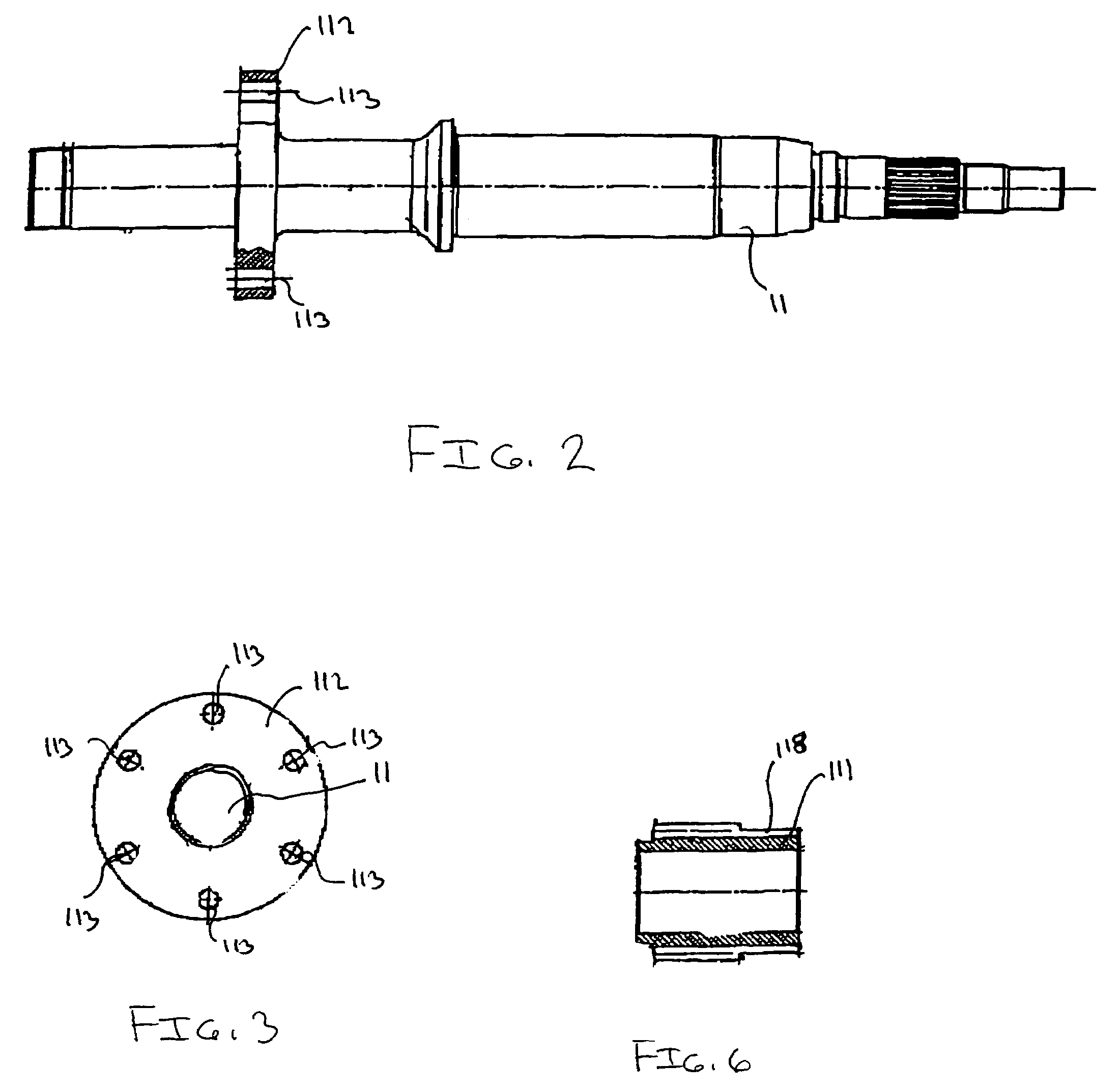
[0022]A reduction of construction costs can be achieved if the driving pinion is mounted on the drive shaft between the overload clutch and a disk spring pack, so as to be able to rotate thereon, and optionally the disk spring pack causes a spring force to act on the driving pinion in the direction of the drive shaft axis, against the overload clutch, in the closing direction of the overload clutch. The at least one friction plate, the at least one clutch plate and the at least one spring can be positioned between the flange and the drive pinion. The spring can be positioned between the flange and either the at least one friction plate or the at least one clutch plate. The at least one spring can alternatively be positioned between the drive pinion and either the at least one friction plate or the at least one clutch plate. It is also contemplated that the drive pinion, the at least one friction plate, and the at least one clutch plate can be positioned between the flange and the at least one spring.
[0024]Such an overload clutch can also be retrofitted to existing drive assemblies by replacing some minor components in existing drive assembly without having to incur any great costs. Using such measures, it is possible to significantly increase the service life of a drive assembly, since the loading on all shafts, wheels, and bearing can be limited to an insignificant maximal value.

Problems solved by technology

One particular problem with this drive concept has been that, in particular when the transmission is subjected to large impact loads in the drive train, such as those that occur, for example, when the vehicle jumps, the gearing will fail or be damaged and possibly destroyed after a number of such load reversals.
These load peaks in the drive assembly are caused in particular because the high moment of inertia of the CVT and the gear ratio of the toothed gearing of the drive assembly make the drive assembly particularly stiff so that it cannot attenuate the load peaks that occur.
This leads to load peaks, in particular at the output of the drive assembly of the output shaft.

Method used


Image

  • Overload coupling
  • Overload coupling
  • Overload coupling

Examples


Embodiment Construction

[0034]A drive assembly 10 for use in connection with an internal combustion engine is illustrated in FIG. 1. The drive assembly 10 can be used in connection with a suitable vehicle including but not limited to an all terrain vehicle, a go-kart, a three-wheeled vehicle, a snowmobile, a motorcycle or any other suitable vehicle. The drive assembly may be incorporated into an all-terrain vehicle such as the ones disclosed in U.S. Pat. Nos. 6,296,073 and 4,699,234, the contents of which are incorporated herein by reference. The drive assembly 10 is operatively connected to the wheel(s) of the vehicle to drive the same.

[0035]The drive assembly 10 includes an input drive shaft 11. The input drive shaft 11 is operatively connected to a driver pulley of a CVT 2, as disclosed, for example, in U.S. patent application Ser. No. 10 / 395,844 entitled “Braking Mechanism for a Gear,” which is assigned to the Assignee of the present application and incorporated herein specifically by reference. The CV...


PUM


Abstract

A drive assembly for a vehicle having at least one wheel and an engine is disclosed. The drive assembly transfers a driving force from the engine to the at least one wheel. The drive assembly includes a rotatable input drive shaft. The input drive shaft is operatively coupled to the engine. The drive assembly further includes a rotatable output drive shaft. The output drive shaft is operatively coupled to the at least one wheel. A first transmission operatively connects the input and output drive shafts. An overload clutch is operatively disposed between the input drive shaft and the first transmission to transfer a driving force from the input drive shaft to the first transmission. The overload clutch may be at least partially mounted to input drive shaft.

Description

CROSS REFERENCE TO RELATED APPLICATION[0001]This application relates to and claims priority to U.S. Provisional Patent Application No. 60 / 443,841, filed on Jan. 31, 2003, which is incorporated herein specifically by reference.BACKGROUND OF THE INVENTION[0002]1. Field of the Invention[0003]The present invention relates to a drive assembly for a vehicle having an overload coupling between a drive shaft and a driving pinion to limit the transmission of excessive and damaging torques through the drive assembly. The overload coupling includes an overload clutch.[0004]2. Description of Related Art[0005]Various manual transmissions for internal combustion engine driven vehicles are known in the art. In a typical arrangement, an internal combustion engine provides a driving force to drive a drive shaft through suitable engine gearing (i.e., drive assembly). This can be accomplished by a belt-driven constant velocity transmission (“CVT”) that acts, preferably through a manual transmission, o...

Claims


Application Information

Patent Timeline
Patent Type & Authority Patents(United States)
IPC IPC(8): B62D21/00B60K17/08F16D7/02
CPCB60K17/08F16D7/025
Inventor WILDFELLNER, KURT
Owner BRP ROTAX
Learn More