Wire cloth

a technology of wire cloth and loom, which is applied in the field of wire cloth, can solve the problems of high production cost and material consumption, and achieve the effects of avoiding excessive weakening of weft wires, reducing material consumption, and reducing production costs

Active Publication Date: 2007-04-17
HAVER & BOECKER
View PDF14 Cites 3 Cited by
  • Summary
  • Abstract
  • Description
  • Claims
  • Application Information

AI Technical Summary

Benefits of technology

[0007]Suitably, the weft wires have a diameter which at least corresponds to the clear distances between two neighboring warp wires. Their diameter may, however, also be greater, as will be described furtherbelow. To ensure clarity, it is necessary to establish the definition of important terms that will be used throughout this disclosure. The term “clear distance” relates to the free spaces and does not refer to the distance between the longitudinal center axes of two neighboring warp wires. It has been surprisingly found that current weaving technology can be used to guide the weft wires through the interstices, even though they may initially appear to narrow. As the weft wires are constricted

Problems solved by technology

However, a problem associated with conventional wire cloths is the need for a great number

Method used


Image

  • Wire cloth
  • Wire cloth

Examples


Embodiment Construction

[0016]Throughout all the Figures, same or corresponding elements are generally indicated by same reference numerals. These depicted embodiments are to be understood as illustrative of the invention and not as limiting in any way. It should also be understood that the drawings are not necessarily to scale and that the embodiments are sometimes illustrated by graphic symbols, phantom lines, diagrammatic representations and fragmentary views. In certain instances, details which are not necessary for an understanding of the present invention or which render other details difficult to perceive may have been omitted.

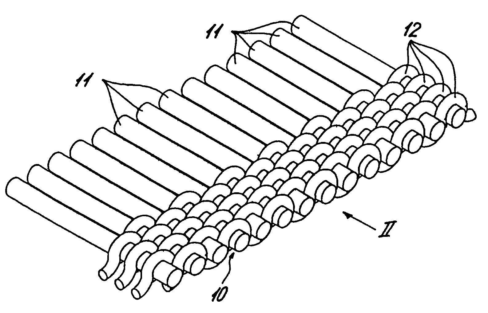
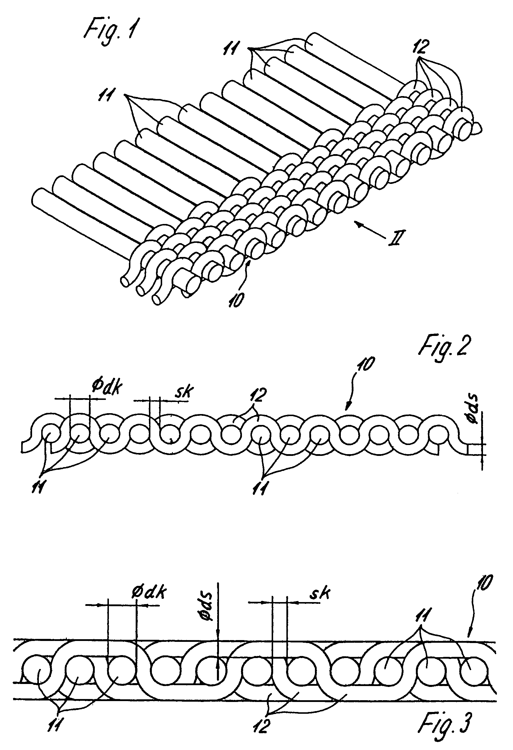
[0017]Turning now to the drawing, and in particular to FIG. 1, there is shown a perspective illustration, on an enlarged, of a portion of a wire cloth according to the present invention, generally designated by reference numeral 10 and woven by a plain weave pattern. The wire cloth portion 10 includes warp wires 11, running in longitudinal direction, and weft wires 12 running ...


PUM

PropertyMeasurementUnit
Diameteraaaaaaaaaa
Diameteraaaaaaaaaa
Diameteraaaaaaaaaa

Abstract

A wire cloth includes metallic warp wires and metallic weft wires interwoven with one another, wherein the weft wires have each a diameter which is equal or smaller than a clear distance between two neighboring warp wires, and wherein the weft wires are constricted in crossing regions with the warp wires.

Description

CROSS-REFERENCES TO RELATED APPLICATIONS[0001]This application claims the priority of German Patent Application, Serial No. 202 17 296.1, filed Nov. 9, 2002, pursuant to 35 U.S.C. 119(a)–(d), the disclosure of which is incorporated herein by reference.BACKGROUND OF THE INVENTION[0002]The present invention relates to a wire cloth, in particular to a filter cloth, having metallic warp wires and metallic weft wires interwoven with one another.[0003]Wire cloths of a type involved here can also be labeled as fine filter cloths as the diameter of the warp wires and the weft wires is at a maximum from 0.1 to 0.2 mm, and at a minimum between 0.02 and 0.03 mm. The number of warp wires ranges between 180 to 500 warp wires per inch, whereas the number of weft wires ranges between 500 to 5000 wires per inch. So-called filtration triangles are obtained through weaving. Heretofore, the interval between the weft wires is smaller than the filtration triangles. The use of warp wires and weft wires w...

Claims


Application Information

Patent Timeline
IPC IPC(8): B21F29/02B21F27/00B21F27/10B21F27/08B01D39/12D03D15/02
CPCB01D39/12D03D15/02Y10T428/2481D10B2101/20Y10T442/116Y10T442/20
Inventor JOHN, DETLEFBUTENKEMPER, STEFAN
Owner HAVER & BOECKER
Why Eureka
Try Eureka