
Parallel flow fractionation tray

a technology of contacting tray and flow fractionation, which is applied in the direction of carburetor air, roof, separation process, etc., can solve the problems of reducing the capacity improving efficiency, etc., and achieves the effect of improving the capacity and increasing the efficiency of the contacting tray

Active Publication Date: 2007-04-17
UOP LLC
View PDF21 Cites 18 Cited by
  • Summary
  • Abstract
  • Description
  • Claims
  • Application Information

AI Technical Summary

Benefits of technology

[0011]Two determinants of the quality of a contacting tray are its efficiency for performing a process and its capacity in terms of liquid or vapor traffic. It is an objective of the subject invention to increase the efficiency of contacting trays with Lewis Case 2 vapor-liquid contacting arrangement. It is another objective of the invention to provide a vapor-liquid contacting apparatus with improved capacity.
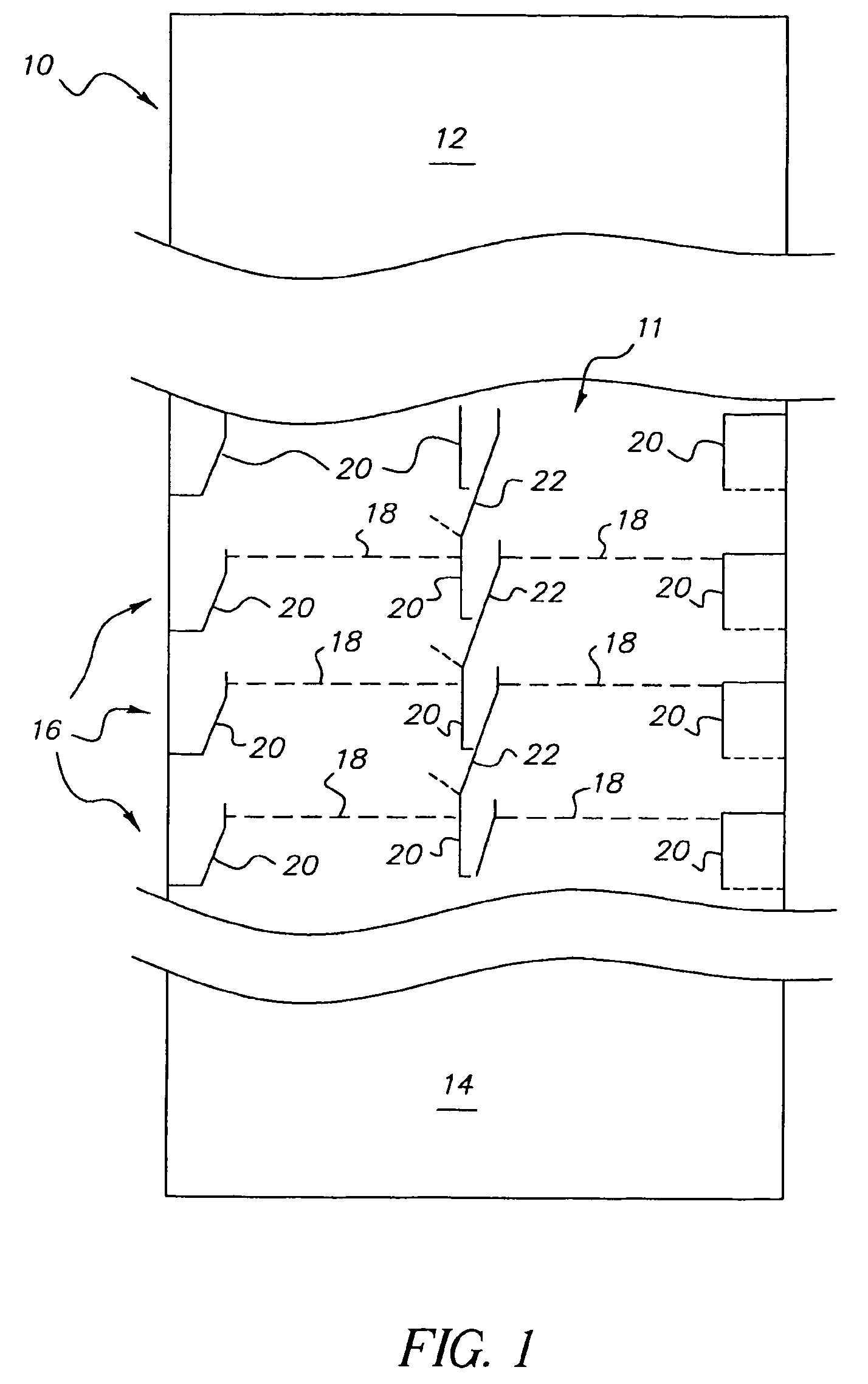
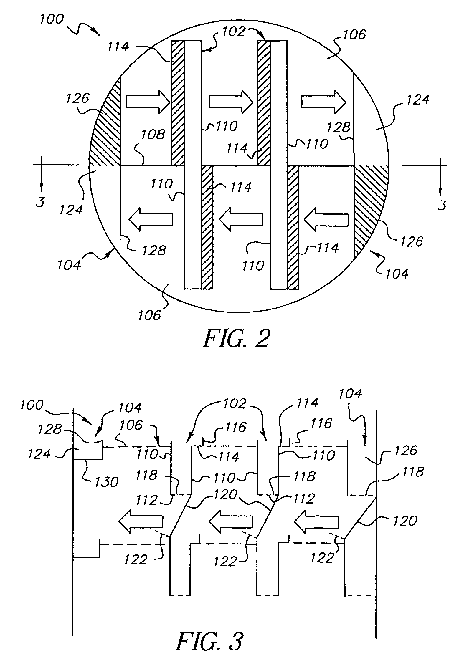
[0017]A still further form of the invention comprises a vapor-liquid contacting tray that has a generally circular circumference and includes at least one centrally located downcomer, a plurality of vapor-liquid contacting decks, and two side downcomers proximate to the outer perimeter of said tray. Each side downcomer has a liquid receiving portion and a liquid distributing portion wherein the receiving portion directs liquid to the distributing portion. A central baffle extends between at least two of the downcomers and intersects at least one of the contacting decks. The central baffle comprises a bend proximate to each of the side downcomers, which increases the size of the liquid receiving portions.

Problems solved by technology

One important issue in the field of vapor-liquid contacting columns is improving the capacity of the trays to allow vapor and liquid to flow from tray to tray without flooding.
A second important issue in the field is improving the efficiency of the trays for mass transfer between vapor and liquid.
Further, froth flow into an outlet downcomer is pinched by the downcomer right above, which may reduce tray capacity.

Method used


Image

  • Parallel flow fractionation tray
  • Parallel flow fractionation tray
  • Parallel flow fractionation tray

Examples


second embodiment

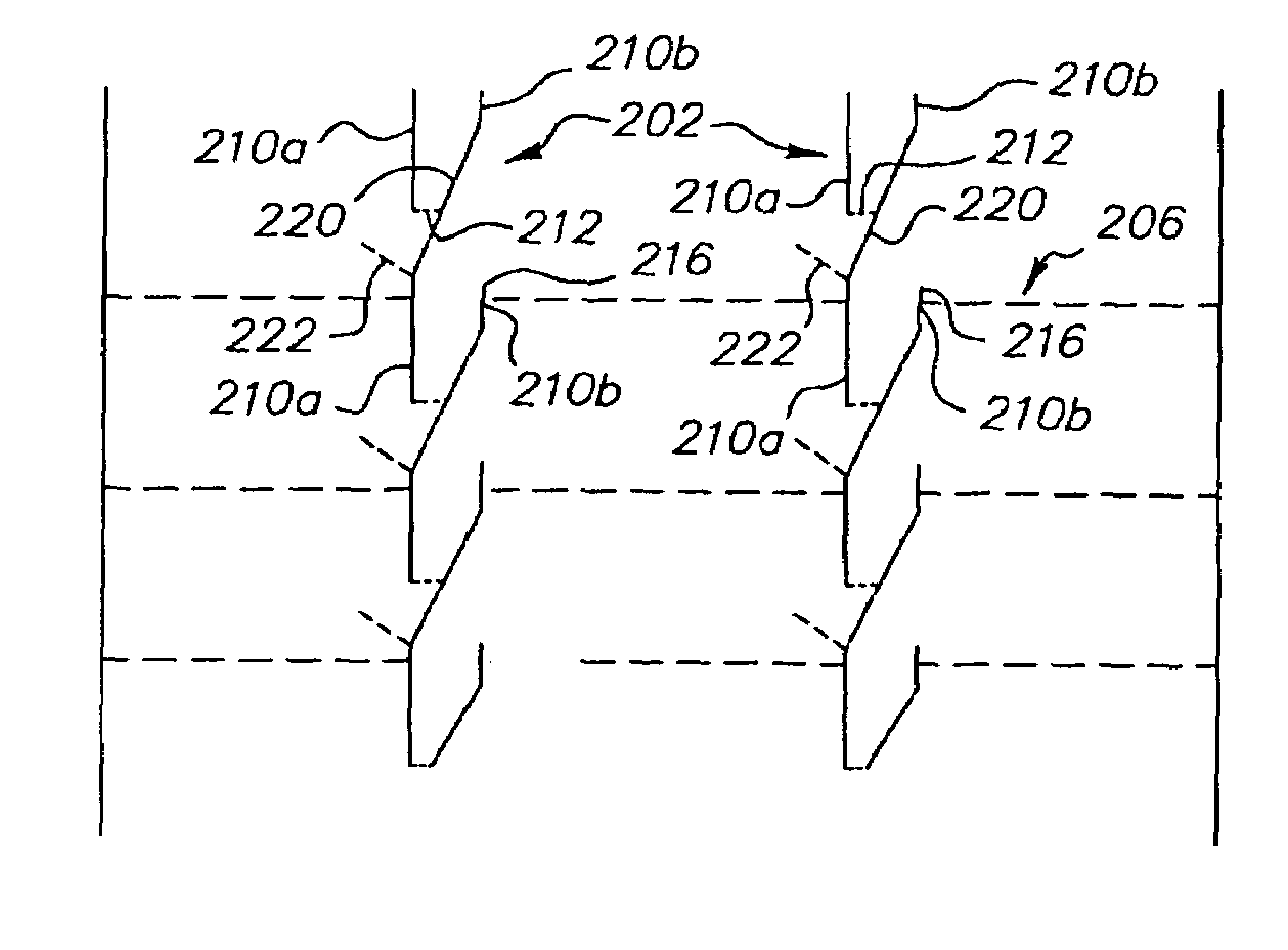
[0042]the invention, shown in FIGS. 6 and 7, includes a tray 200 having at least one central downcomer 202. Each central downcomer 202 includes a side wall 210a, a shortened side wall 210b, a bottom plate 212, an inlet weir 216 defined by the portion of side wall 210b above the deck 206, a liquid balancing box 234, and an inclined baffle 220 with an anti-penetration weir 222. The bottom plate 212 includes openings 218 for the exit of the liquid which accumulates within the central downcomer 202. In this embodiment, the inclined baffle 220 is incorporated into one side wall 210b to form a sloped downcomer that provides additional volume above the inlet to the central downcomer 202. The extension of the shortened side wall 210b below the decking can improve tray strength and aid in supporting the decking. However, extension of the shortened side wall 210b below the decking is not required. Thus, if the first side wall extends below the decking and the second side wall does not extend ...

first embodiment

[0043]As described in the first embodiment, strengthened central downcomers may be used for additional support for the tray 100. The central downcomers may provide the majority of the support for the contacting tray 200 and since tray efficiency is increased with fewer central downcomers, strengthened central downcomers 202 may be needed. Strengthened central downcomers 202, as shown in FIGS. 8A and 8B, may be made with two pieces (one with an inclined baffle 220 slanted one way and the other slanted in the opposite direction). Each piece may be made mostly of a single sheet of material that is cut and bent into shape. Thus there are as few joints as possible. The pieces each have a flange 254 that overlaps with the shortened side wall 210b and the inclined baffle 220 of the opposite piece and cooperates to form a strong joint between the two pieces and also to form a modified liquid balancing box 234 that facilitates fluid transfer between the downcomer sections. The flanges 254 di...


PUM

PropertyMeasurementUnit
hole diameteraaaaaaaaaa
hole sizeaaaaaaaaaa
thicknessaaaaaaaaaa

Abstract

The invention comprises multiple configurations of downcomers in a parallel flow multiple downcomer tray for vapor-liquid contacting processes such as the separation of chemical compounds via fractional distillation or the removal of a component of a gas stream with a treating liquid. In one embodiment, side downcomers are incorporated into a parallel flow multiple downcomer tray. In another embodiment, the downcomers have an inclined side wall that directs liquid onto the deck below the downcomer. The inclined side wall also provides additional volume above the inferior downcomer inlet to reduce pinching at this inlet without the need for a stilling deck.

Description

FIELD OF THE INVENTION[0001]This invention relates to vapor-liquid contacting apparatus and specific features that improve the efficiency and capacity of this operation. The invention therefore relates to, for example, apparatus used as fractionation trays within fractional distillation columns. The invention may also be used in a variety of other gas-liquid contacting operations such as acid gas scrubbing or absorption processes.BACKGROUND OF THE INVENTION[0002]Fractional distillation columns having a number of vertically spaced distillation trays are widely employed in the hydrocarbon processing, chemical, and petrochemical industries. Accordingly, a large amount of research, development, and creative thinking has been devoted to providing improved fractional distillation trays. Fractionation tray development has therefore provided many variations in contacting area structure, downcomer design, and overall tray structure.[0003]Vapor-liquid contacting devices are used in a wide var...

Claims


Application Information

Patent Timeline
Patent Type & Authority Patents(United States)
IPC IPC(8): B01F3/04B01F23/00B60J10/90
CPCB01D3/20B01D3/008B01F23/20B01F25/00
Inventor XU, ZHANPINGMONKELBAAN, DANIEL R.NOWAK, BRIAN J.MILLER, ROBERT J.
Owner UOP LLC
Learn More