Wafer holding, wafer support member, wafer boat and heat treatment furnace

Inactive Publication Date: 2007-04-17
NIPPON STEEL CORP
View PDF12 Cites 377 Cited by
  • Summary
  • Abstract
  • Description
  • Claims
  • Application Information

AI Technical Summary

Benefits of technology

[0023]The present inventors actually fabricated wafer holders based on the above two ideas and conducted high temperature heat treatment of silicon wafers using the fabricated wafer holders. As a result, they confirmed that the occurrence of the slip dislocations caused by both the weight of the wafer and the thermal deformation of the wafer support plate could be suppressed.
[0024]The present inventors also earnestly studied the structure of a wafer holder satisfying the requirements (2) and (3) and, as a result of close examination into the relation between the structure of a wafer holder and the occurrence of slip dislocations during heat treatment, discovered the following: the larger the contact area of the wafer with the wafer holder, the larger the number of contact portions where the welding of the wafer and the wafer holder occurred during the heat treatment; but, even when the welding occurred, the smaller the deformation of the wafer holder during the heat treatment, the less the slip dislocations occurred; and, as a co

Problems solved by technology

As a consequence, a large bending stress is imposed on the wafer at the vicinity of the support parts during the high temperature heat treatment employed in the production of the SIMOX wafers, annealed wafers and the like, and, if the stress exceeds the yield stress of the silicon wafer at the temperature of the heat treatment, there is a problem that defects called slip dislocations occur inside the wafer during the heat treatment.
Even by this technology, however, the occurrence of slip dislocations is not suppressed sufficiently.
Even by this technology, however, the silicon balls still weld with the silicon wafer during the heat treatment in an oxidizing atmosphere employed for the production of SIMOX annealed wafers, and the slip dislocations of the wafer caused by the thermal deformation of the wafer support plate cannot be suppressed sufficiently.
Besides, as the wafer support plate does not have a notch, the wafer conveying apparatus tends to be large, and the wafer charging and discharging movements of the wafer conveying apparatus requires large spaces above and beneath the wafer support plate.
As a result, the wafer conveying movements of the wafer conveying apparatus become complicated and the wafer conveying time becomes longer and, therefore, the productivity of the heat treatment furnace per batch is lowered.
A yet more serious problem is that, using this technology, one third of the weight of the wafer is concentrated at a support part, and the stress resulting from the wafer weight causes the slip dislocations of the wafer at the supported portions of the wafer.

Method used


Image

  • Wafer holding, wafer support member, wafer boat and heat treatment furnace
  • Wafer holding, wafer support member, wafer boat and heat treatment furnace
  • Wafer holding, wafer support member, wafer boat and heat treatment furnace

Examples


Example

EXAMPLE

[0138]Examples of the present invention are explained hereafter.

Example

Invented Example 1, Comparative Example 1

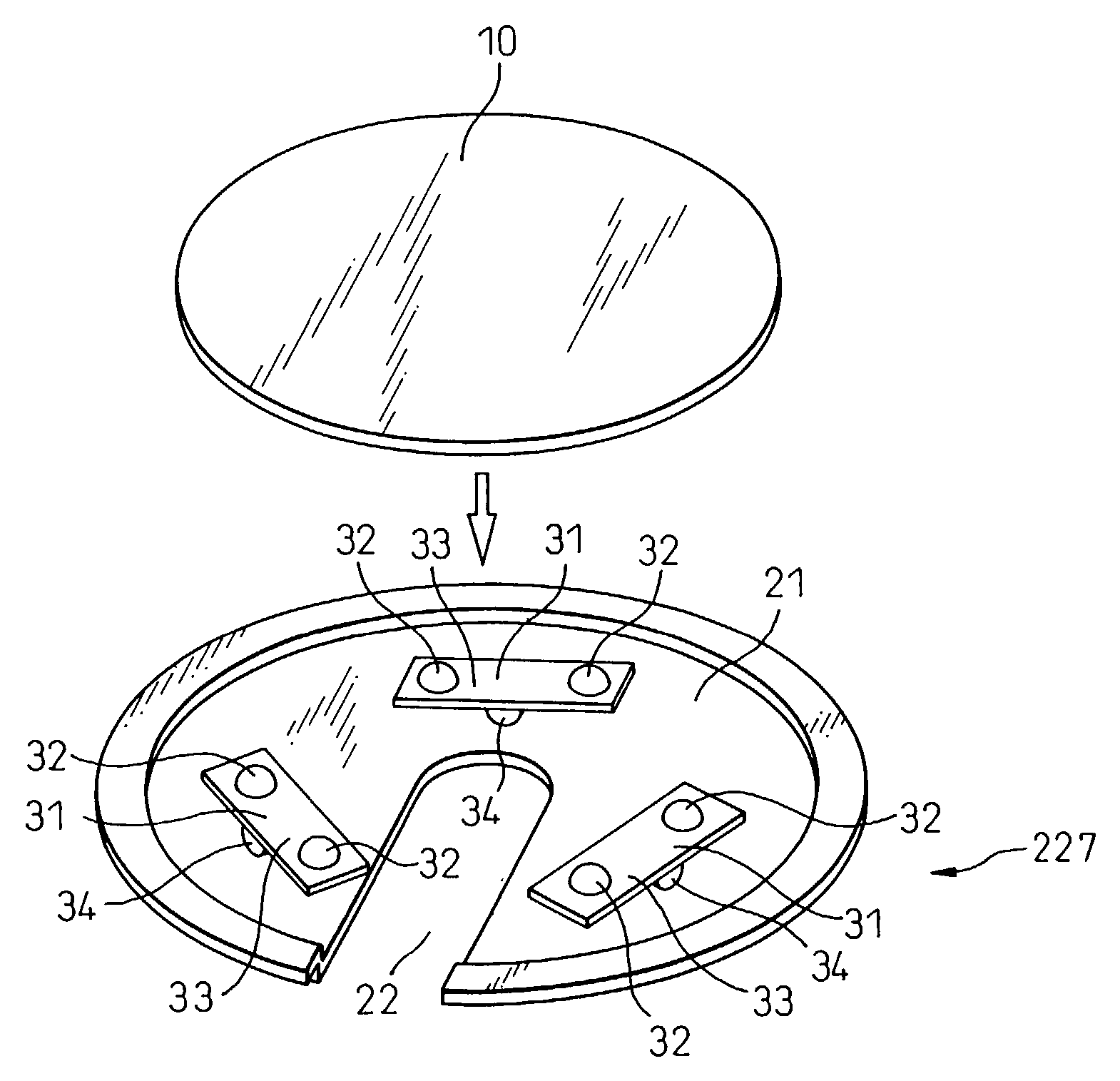
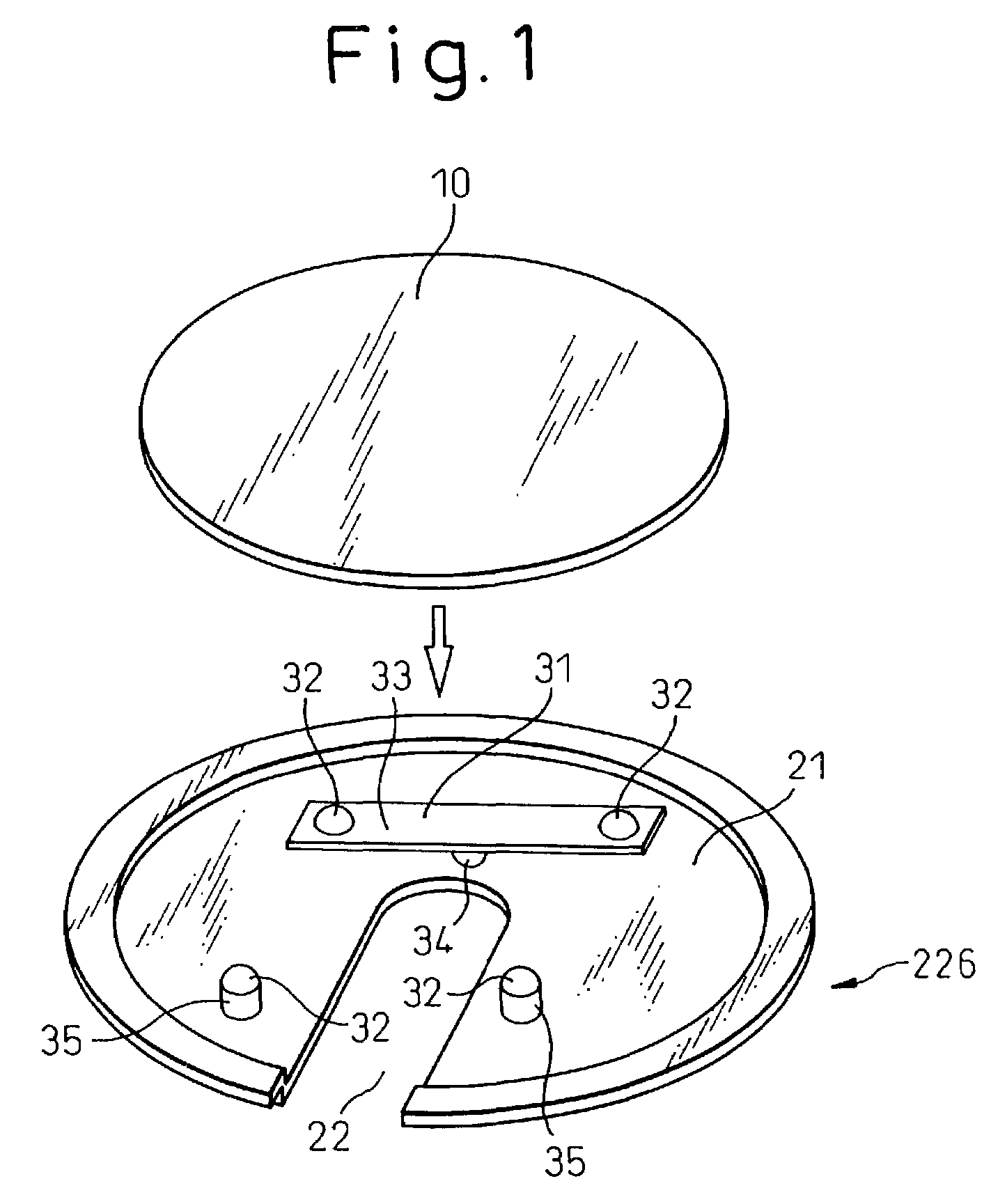
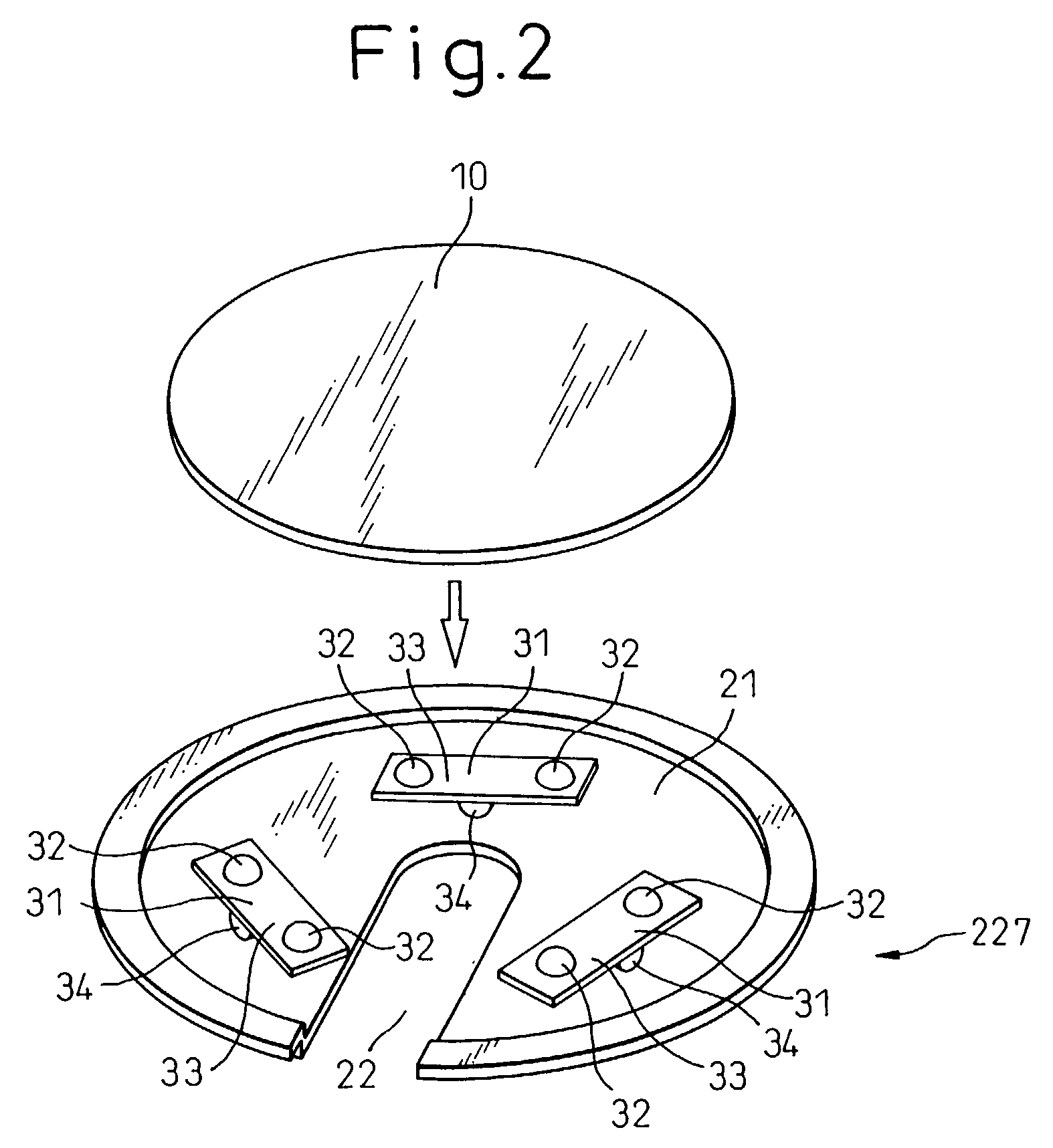
[0139]The present inventors carried out a test to confirm whether the first wafer holder, the wafer boat and the heat treatment furnace according to the present invention would demonstrate intended effects. The tilting wafer support members 31, 36, 38, 41, 46, 51, 55, 56 and 61 and the fixed wafer support members 35 shown in FIGS. 1 to 7 were used for the test.

[0140]When fabricating the above-mentioned types of tilting wafer support members, the distance between the wafer support portions 32 provided on the upper surfaces of the tilting wafer support members was set within the range from 5 to 40 mm. The various types of the tilting wafer support members were disposed on the upper surface of the wafer support plate 21 at positions distant from the center of the wafer support plate 21 by about 70% of the radius of the wafer 10. Also, the tilting wafer support members were disposed in a manner that the polygon obtained by connecting the centers ...

Example

Inventive Example 2, Comparative Example 2

[0146]The present inventors carried out a test to confirm whether the second wafer holder, the wafer boat and the heat treatment furnace according to the present invention would demonstrate intended effects. The support members fabricated for the test were of the type shown in FIG. 10 and, to be concrete, each of them had an upper structure and a lower structure made of SiC and shaped in hemispheres having a diameter of 10 mm, a height of 5 mm and a radius of curvature of 5 mm, and a middle structure made of quartz glass and shaped in a cylindrical column having a diameter of 10 mm and a height of 5 mm. The upper, middle and lower structures were put together as one piece. Support members made of SiC of about the same size as the above integrated support members were also fabricated and used for the test. The wafer holders used for the test were of the type shown in FIG. 8, having a disc shape and made of SiC. The wafer holders shown in FIG....


PUM

PropertyMeasurementUnit
Timeaaaaaaaaaa
Radiusaaaaaaaaaa
Diameteraaaaaaaaaa

Abstract

The present invention provides a wafer holder, a wafer support member, a wafer boat and a heat treatment furnace, which are capable of sufficiently suppressing slip dislocations, without lowering productivity and at low cost, in the high temperature heat treatment of silicon wafers, and said wafer holder is characterized in that: the wafer holder is composed of a wafer support plate and three or more wafer support members mounted on said wafer support plate, each of the wafer support members having a wafer support portion or more; at least one of said wafer support members is a tilting wafer support member which has a plurality of upward-convex wafer support portions on the upper surface and is tiltable with respect to said wafer support plate; and the wafer is supported by at least four wafer support portions.

Description

TECHNICAL FIELD[0001]This invention relates to a wafer holder, a wafer support member, a wafer boat and a heat treatment furnace suitable for the heat treatment of silicon wafers and, especially, for the high temperature heat treatment employed in the production of SIMOX (Separation by IMplanted OXygen) wafers, annealed wafers and the like.BACKGROUND ART[0002]A vertical-type heat treatment furnace has come to be used as the heat treatment apparatus of silicon wafers in view of the recent trend toward larger diameter silicon wafers. A vertical wafer boat having a plurality of vertical support columns is installed in the vertical type heat treatment furnace, and the wafers are heat-treated after being inserted in a plurality of support grooves cut in the inside walls of the support columns. By this supporting method, however, each wafer is supported by wafer support parts disposed along the outermost periphery of the wafer, and the weight of the wafer is imposed on the wafer only at t...

Claims


Application Information

Patent Timeline
IPC IPC(8): H01L21/00C23C16/00H01L21/673H01L21/687
CPCH01L21/67309H01L21/68735H01L21/6875Y10S206/832
Inventor KAWAMURA, KEISUKESASAKI, TSUTOMUMATSUMURA, ATSUKIIKARI, ATSUSHIHAMAGUCHI, ISAOINOUE, YOSHIHARUTANAKA, KOKIHAYASHI, SHUNICHI
Owner NIPPON STEEL CORP
Why Eureka
Try Eureka