Spiral cold cathode fluorescent lamp

a fluorescent lamp and cold cathode technology, applied in the direction of vacuum obtaining/maintenance, discharge tube luminescnet screens, gas-filled discharge tubes, etc., can solve the problems of gas absorber, ccfl cannot serve the purpose of illumination, cold cathode fluorescent lamps to decay, etc., to prolong the life of lights, increase the life of ccfl, and increase the intensity.

Inactive Publication Date: 2007-04-17
TECHN CONSUMER PRODS
View PDF9 Cites 14 Cited by
  • Summary
  • Abstract
  • Description
  • Claims
  • Application Information

AI Technical Summary

Benefits of technology

[0022]To cope with this problem of oxidation, one method employed is to place a gas absorber in the light tube to absorb the oxygenic gas. The less the oxygenic gas exists in the light tube, the slower the cold cathode oxidizes, which results in the cold cathode being able to emit electrons with sufficient intensity longer. Hence, the life span of the CCFL is therefore increased.
[0023]For example, a conventional color display may adopt a cathode partially coated with a layer of gas absorbent based upon an alloy of barium; and the filament of an electric light bulb may contain a gas absorber having phosphor as its predominating constituent; and some high-end products of CFL may include a gas absorber made of an alloy containing zirconium and aluminum. These various types of gas absorbers serve the same purpose of absorbing oxygenic gas in order to lengthen the life span of the lights.
[0024]One shortcoming of the conventional gas absorber is its insufficient capability of absorbing the oxygenic gas. The gas absorber usually performs at an activation temperature as high as 900 degrees Celsius. The high activation temperature works in both ways. Although it helps the absorber to absorb the oxygenic gas, it facilitates the oxidizing reaction of the cathode.

Problems solved by technology

The one phenomenon that causes a cold cathode fluorescent lamp to decay over time is its inherent problem with oxidation.
At this point, the CCFL can no longer serve its purpose of illumination.
One shortcoming of the conventional gas absorber is its insufficient capability of absorbing the oxygenic gas.

Method used


Image

  • Spiral cold cathode fluorescent lamp
  • Spiral cold cathode fluorescent lamp
  • Spiral cold cathode fluorescent lamp

Examples


Embodiment Construction

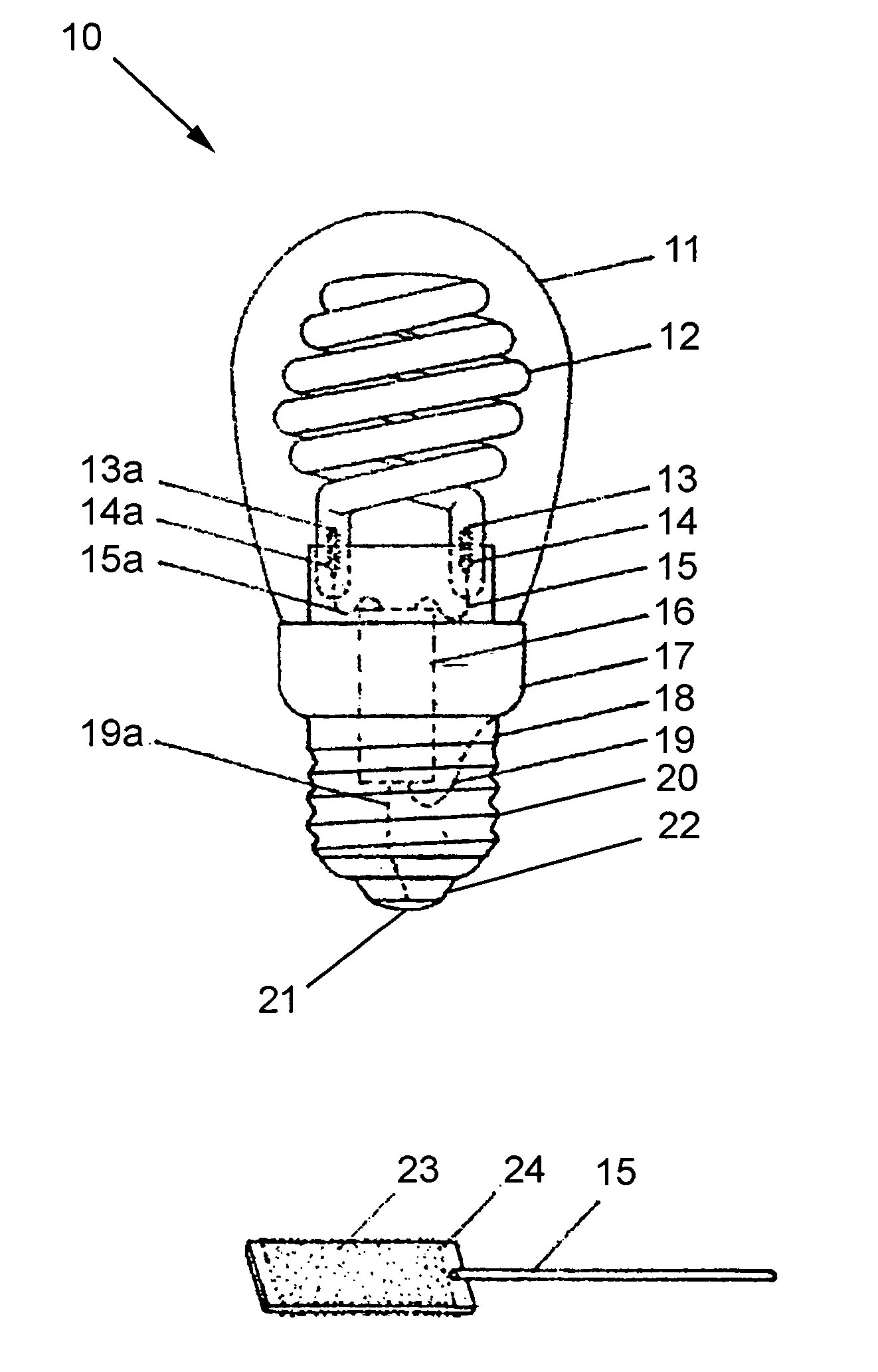
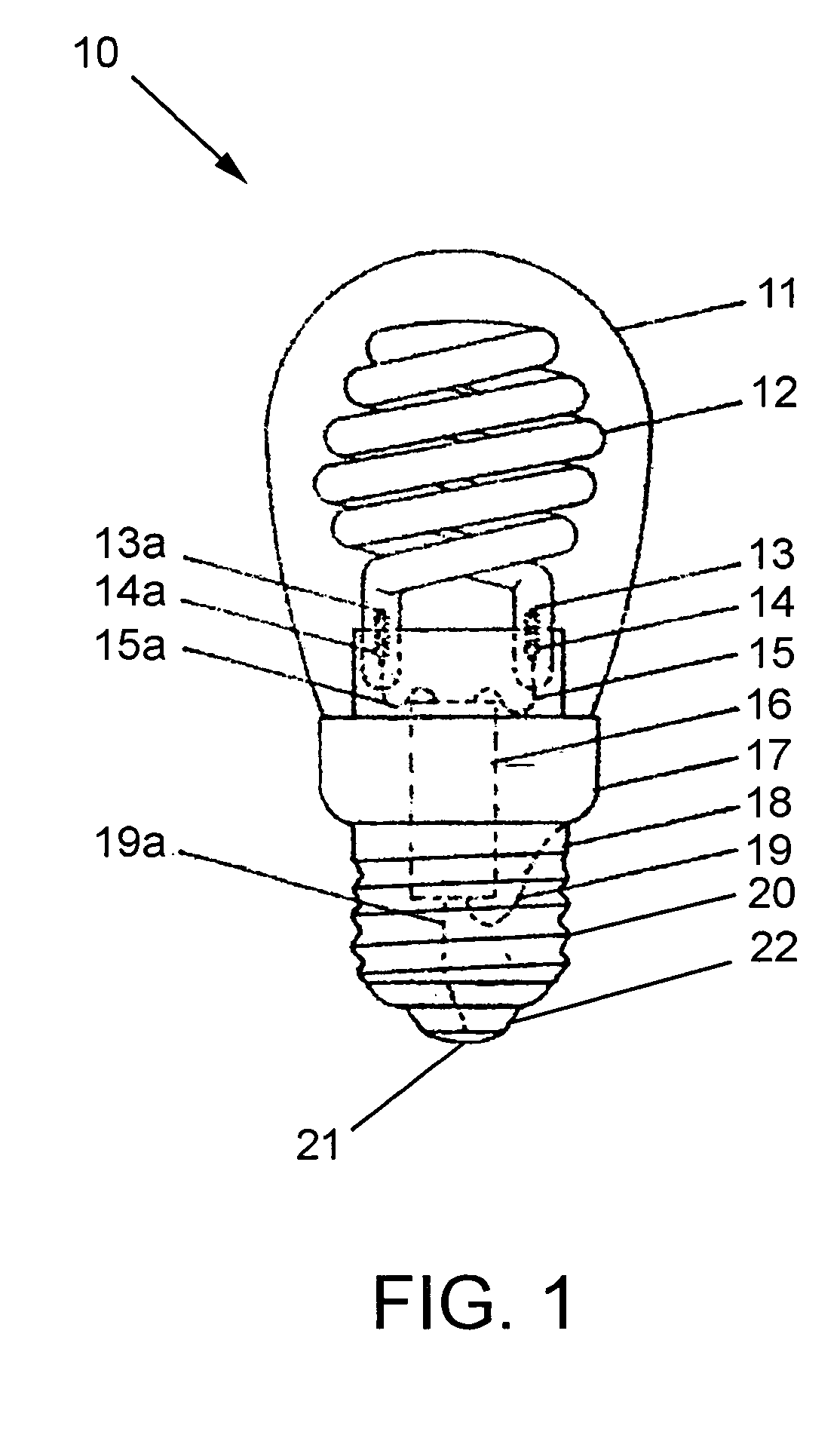
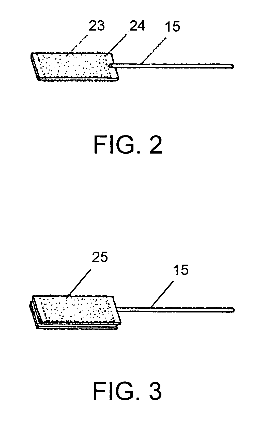
[0038]FIG. 1 is a side view of a cold cathode fluorescent lamp, a CCFL that includes a gas absorber in accordance with the preferred embodiment of the present invention. The CCFL 10 is comprised of a base 18, an igniter casing 17 that extends from the base 18, an igniter 16 disposed in the igniter casing 17, electrodes including a cathode 13 and an anode 13a, activated gas absorbers 14 and 14a, a light tube 12 containing the electrodes 13 and 13a, and a housing envelope 11 attached to the igniter casing 17 for enclosing the light tube 12 therein.

[0039]The base 18 is comprised of a threaded sidewall connector 20, having a cylindrical shape, and an electrical foot contact 21, adapted for securing to a compatible socket for electrically connecting to an electric power source. The threaded sidewall connector 20 and the electrical foot contact 21 are made of conductive material for electrically connecting to the socket. The threaded sidewall connector 20 and electrical foot contact 21 ar...


PUM


Abstract

A light tube for a cold cathode fluorescent lamp includes a light tube body, anode and cathode disposed in the light tube body and an activated gas absorber. The light tube body contains inert gas, mercury substance and a layer of phosphor coating on its inner surface. The cathode is adapted for electrically connecting to the negative terminal for emitting electrons to excite the mercury substance for conducting the electrons to the anode as an electric circuit, wherein the excited mercury substance emits ultra violet rays causing the phosphor coating to generate visible light. The activated gas absorber is gas absorber made of zirconium-aluminum alloy which can be activated at an activation temperature substantially lower than 900 degrees Celsius, preferably 390 degrees Celsius, to provide stronger oxygenic gas absorption ability while reducing the manufacturing steps and cost.

Description

FIELD OF INVENTION[0001]The present invention relates primarily to a spirally wound cold cathode fluorescent lamp, and more particularly to a spirally wound cold cathode fluorescent lamp whose cathode is coated with a layer of a gas absorbent alloy for slowing the oxidizing decay rate of the cathode.BACKGROUND OF THE INVENTION[0002]A compact fluorescent lamp (CFL) is widely used for lighting. A conventional CFL includes a light tube, having a phosphor coating on its inner surface, and containing an inert gas and mercury substance, where the mercury is in the form of mercury vapor or liquid mercury. The light tube is enclosed with caps at its two ends, at which a cathode and anode are disposed therein. When enough electric voltage is applied to the cathode and anode, the cathode emits electrons and causes the mercury to discharge, thereby conducting the electric current to the anode. In the course of discharge, the mercury emits ultraviolet rays that excite the phosphor coating to ge...

Claims


Application Information

Patent Timeline
Patent Type & Authority Patents(United States)
IPC IPC(8): H01J1/62H01J63/04H01J61/26H01J61/30H01J61/32
CPCH01J61/26H01J61/307H01J61/327
Inventor YAN, ELLIS
Owner TECHN CONSUMER PRODS
Why Eureka
Try Eureka