Power amplifier

a power amplifier and pulse width technology, applied in single-ended push-pull amplifiers, gain control, phase splitters, etc., can solve the problems of 4 not being able to provide the minimum and maximum power amplifier output at a desired ratio, and the speaker may be broken down (burnt out), so as to achieve the effect of novel power amplifiers

Inactive Publication Date:
View PDF22 Cites 8 Cited by
  • Summary
  • Abstract
  • Description
  • Claims
  • Application Information

AI Technical Summary

Problems solved by technology

At this time, the speaker will possibly be broken down (burnt out).
Thus, the circuit construction shown in FIG. 4 cannot provide minimum and maximum power amplifier outputs at a desired ratio.

Method used


Image

  • Power amplifier
  • Power amplifier
  • Power amplifier

Examples


Embodiment Construction

[0054]The present invention will be described concerning embodiments in which the present invention is applied in the aforementioned digital audio signal power amplifier.

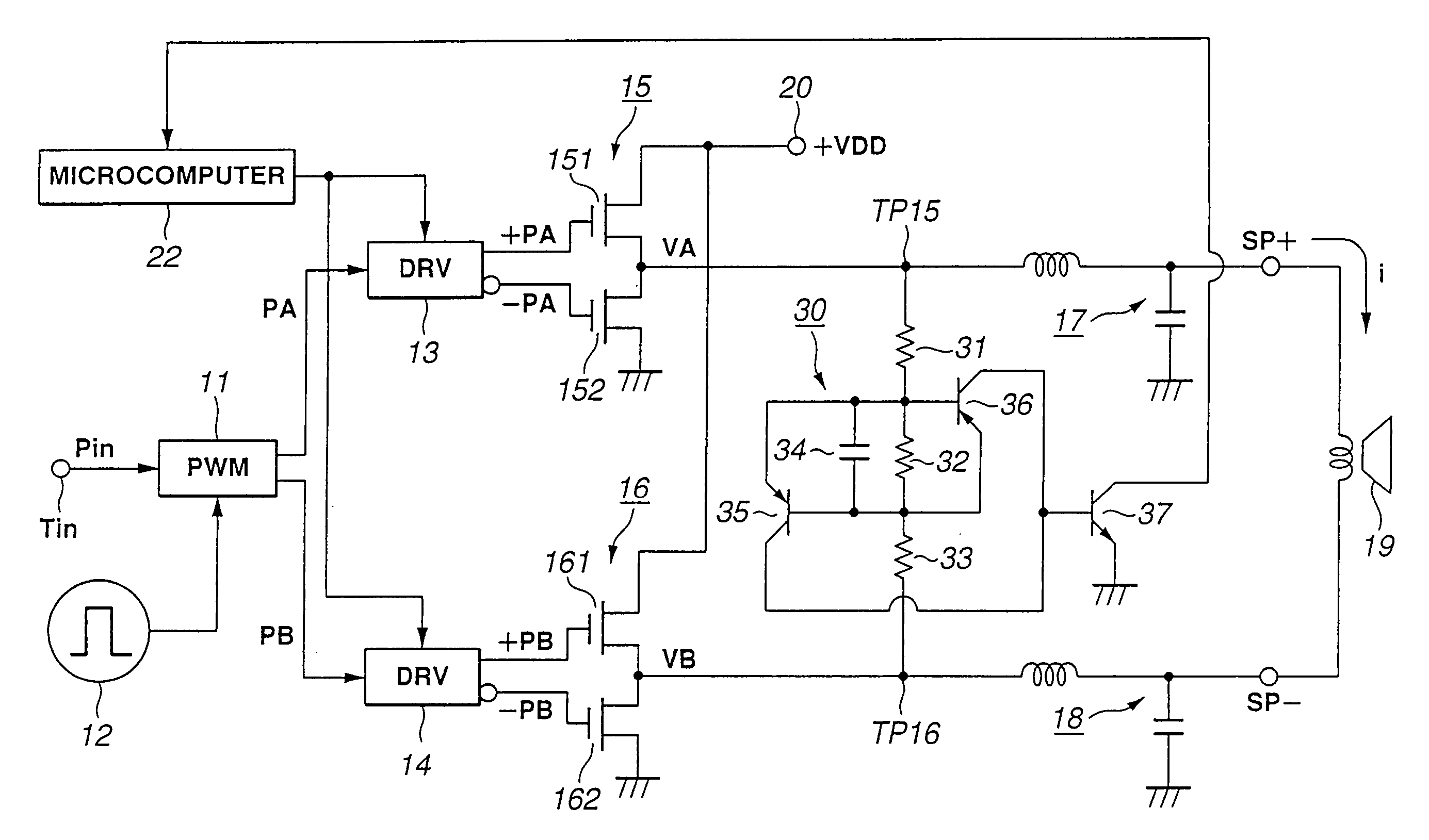
[0055]FIG. 5 is a circuit diagram of the power amplifier according to the present invention, showing the construction of the latter. The PWM-driven circuit part except for the overcurrent detection circuit part is quite the same as in FIG. 1.

[0056]In the power amplifier according to the present invention, a source voltage +VDD from a power terminal 20 is supplied, not via any resistor but directly, to push-pull circuits 15 and 16, differently from the conventional power amplifier having been described with reference to FIG. 4.

[0057]As shown, the overcurrent detection circuit, generally indicated with a reference 30, included in the power amplifier according to the present invention includes push-pull circuits 15 and 16 and a series circuit from resistors 31, 32 and 33 connected between a junction TP 15 between the s...


PUM


Abstract

In a power amplifier driven by a pulse width modulation (PWM) signal, a first pair of drive pulses opposite in level to each other is formed from a first pulse width modulation signal whose quantization level corresponds to its pulse width and supplied to a first push-pull circuit (15). A second pair of drive pulses opposite in level to each other is formed from a second pulse width modulation signal whose two's complement of quantization level corresponds to its pulse width, and supplied to a second push-pull circuit (16). A speaker (19) is connected between the first and second push-pull circuits (15 and 16). A deviation between potentials at the output terminals of the first and second push-pull circuits (15 and 16), respectively, is detected. When a deviation is detected, the push-pull circuits are substantially stopped from operating.

Description

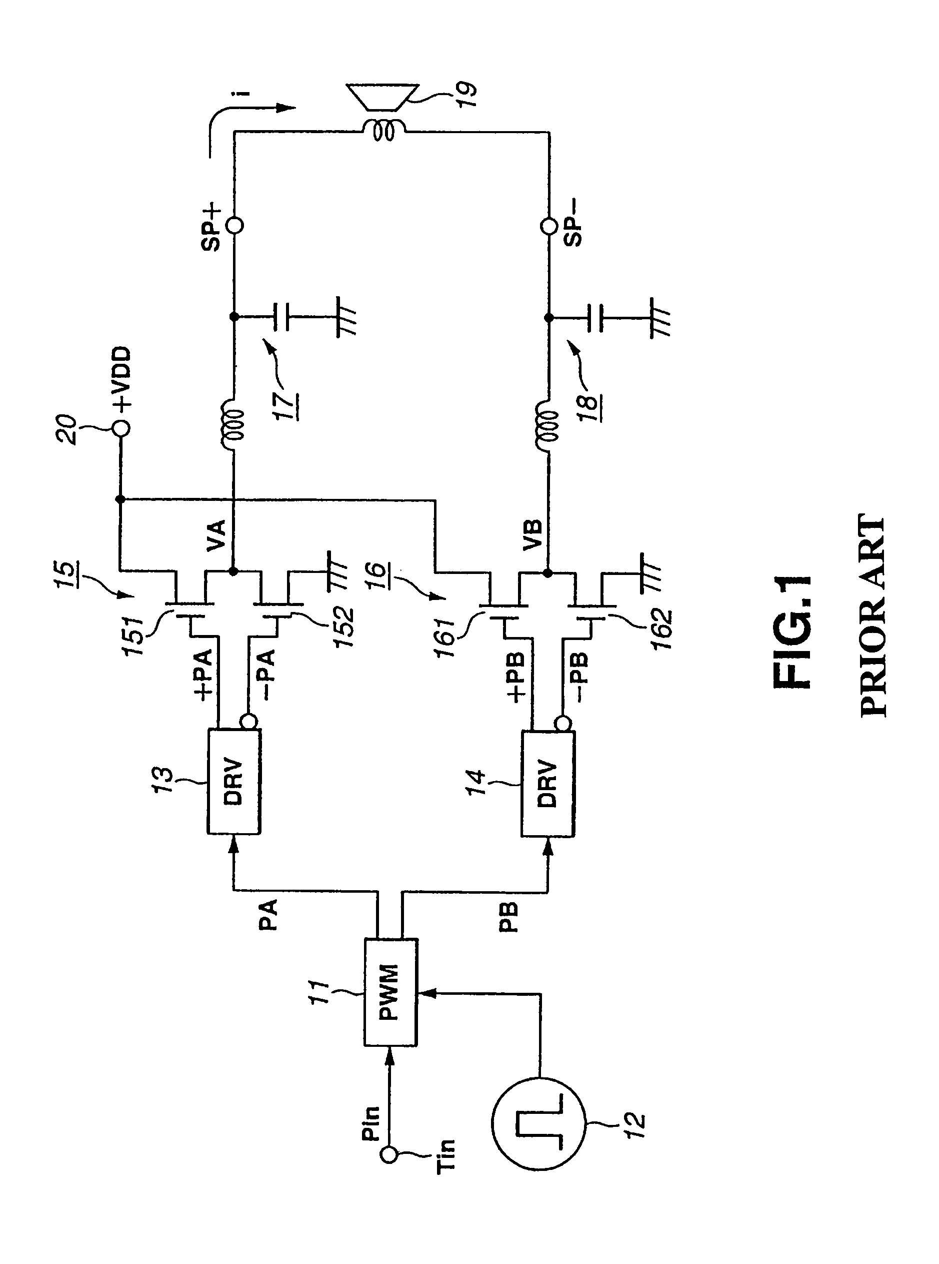
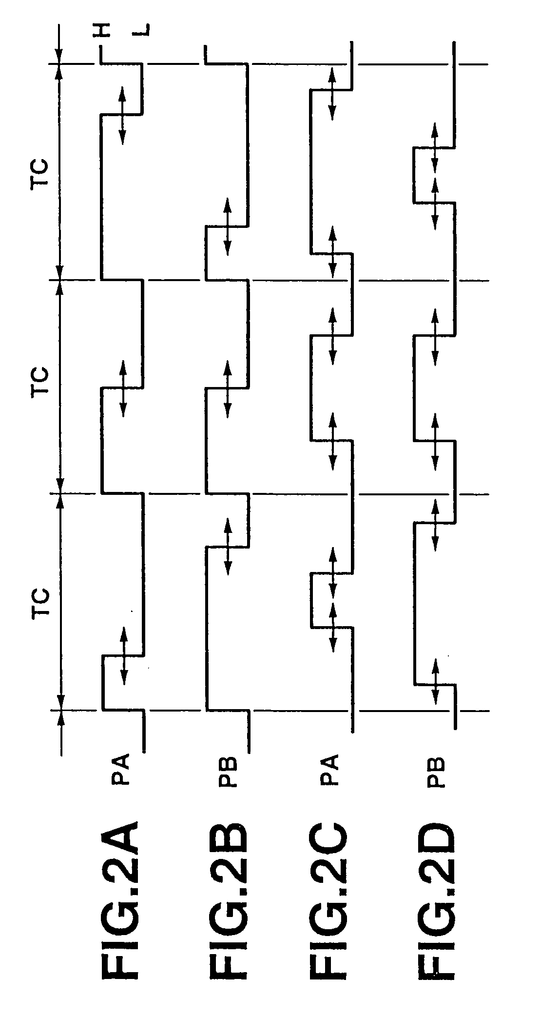
TECHNICAL FIELD [0001]The present invention relates to a pulse width modulation (PWM) signal-driven power amplifier.[0002]This application claims the priority of the Japanese Patent Application No. 2002-209557 filed on Jul. 18, 2002, the entirety of which is incorporated by reference herein.BACKGROUND ART [0003]Conventionally, there is available a digital amplifier called “D-class amplifier” as an audio power amplifier. The D-class amplifier amplifies a power by switching, and it is constructed as shown in FIG. 1 for example.[0004]In the power amplifier shown in FIG. 1, digital audio signal Pin is supplied to a PWM circuit 11 via an input terminal Tin, and clock signal having a predetermined frequency is supplied from a clock generator 12 to the PWM circuit 11. The digital audio signal Pin supplied to the PWM circuit 11 is converted into a pair of PWM signals PA and PB.[0005]As shown in FIGS. 2A and 2B the pulse width of the PWM signals PA and PB, or a time duration for which the wa...

Claims


Application Information

Patent Timeline
Patent Type & Authority Patents(United States)
IPC IPC(8): H03F3/38H03F1/52H03F3/04H03F3/217
CPCH03F3/2173H03F3/217H03F3/26
Inventor GOTO, MASAO
Why Eureka
Try Eureka