Light source and display device

a technology which is applied in the field of light source and display image, can solve the problems of greatly reduced luminance, achieve the effects of suppressing the brightness of the display image, increasing the temperature of the elements, and reducing luminan

Inactive Publication Date: 2007-04-17
SEIKO EPSON CORP
View PDF54 Cites 90 Cited by
  • Summary
  • Abstract
  • Description
  • Claims
  • Application Information

AI Technical Summary

Benefits of technology

[0049]In the display device according to any one of (17) to (19), advantages are achieved more remarkably, in that a rise in the temperature of the elements due to the accumulation of heat in the organic electroluminescent elements can be suppressed, and a decrease in luminance, namely, a decrease in the brightness of the display image, can be suppressed.

Problems solved by technology

However, when the organic EL element is continuously operated with increased luminance, the luminance becomes greatly decreased.

Method used


Image

  • Light source and display device
  • Light source and display device
  • Light source and display device

Examples


first embodiment

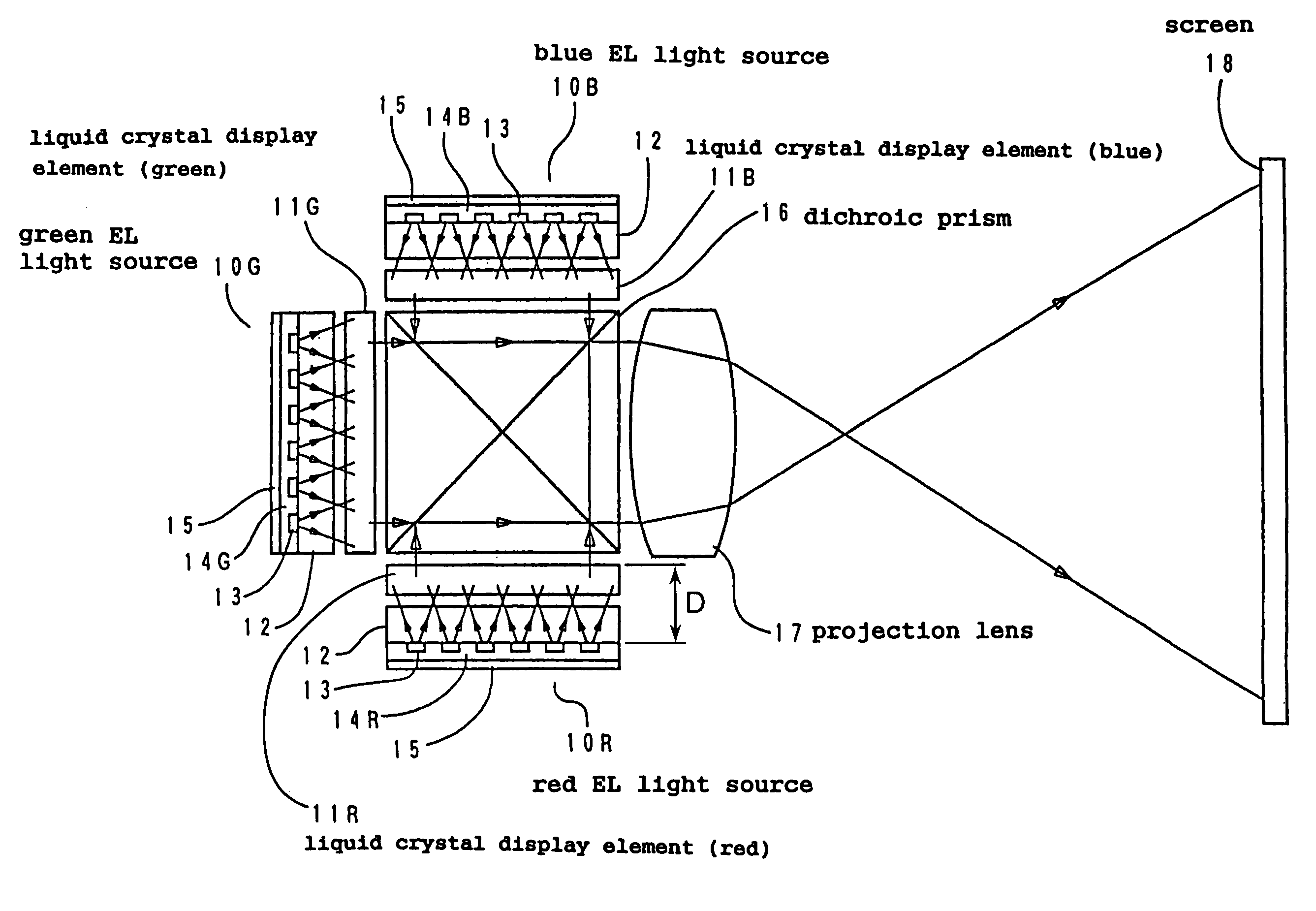
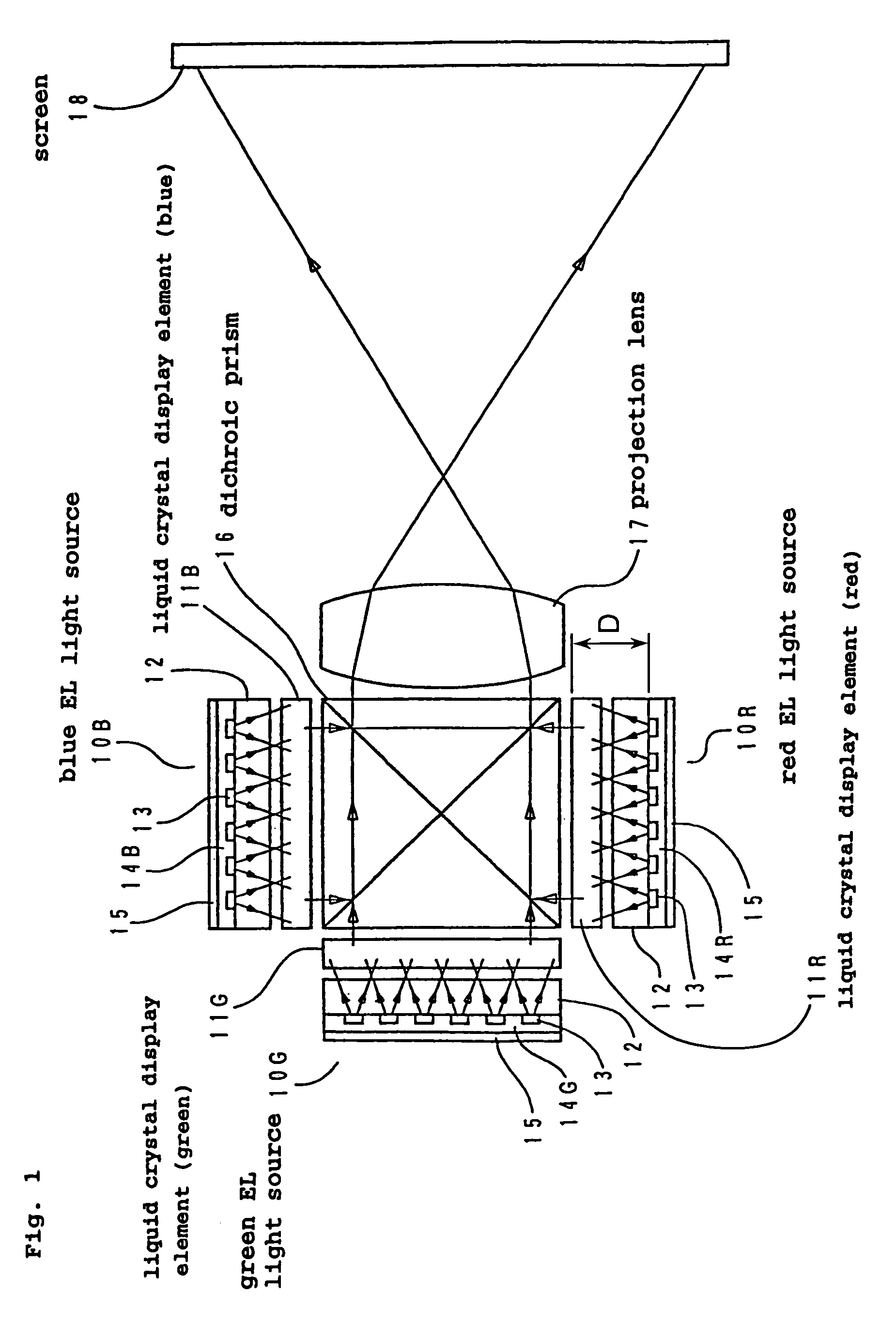
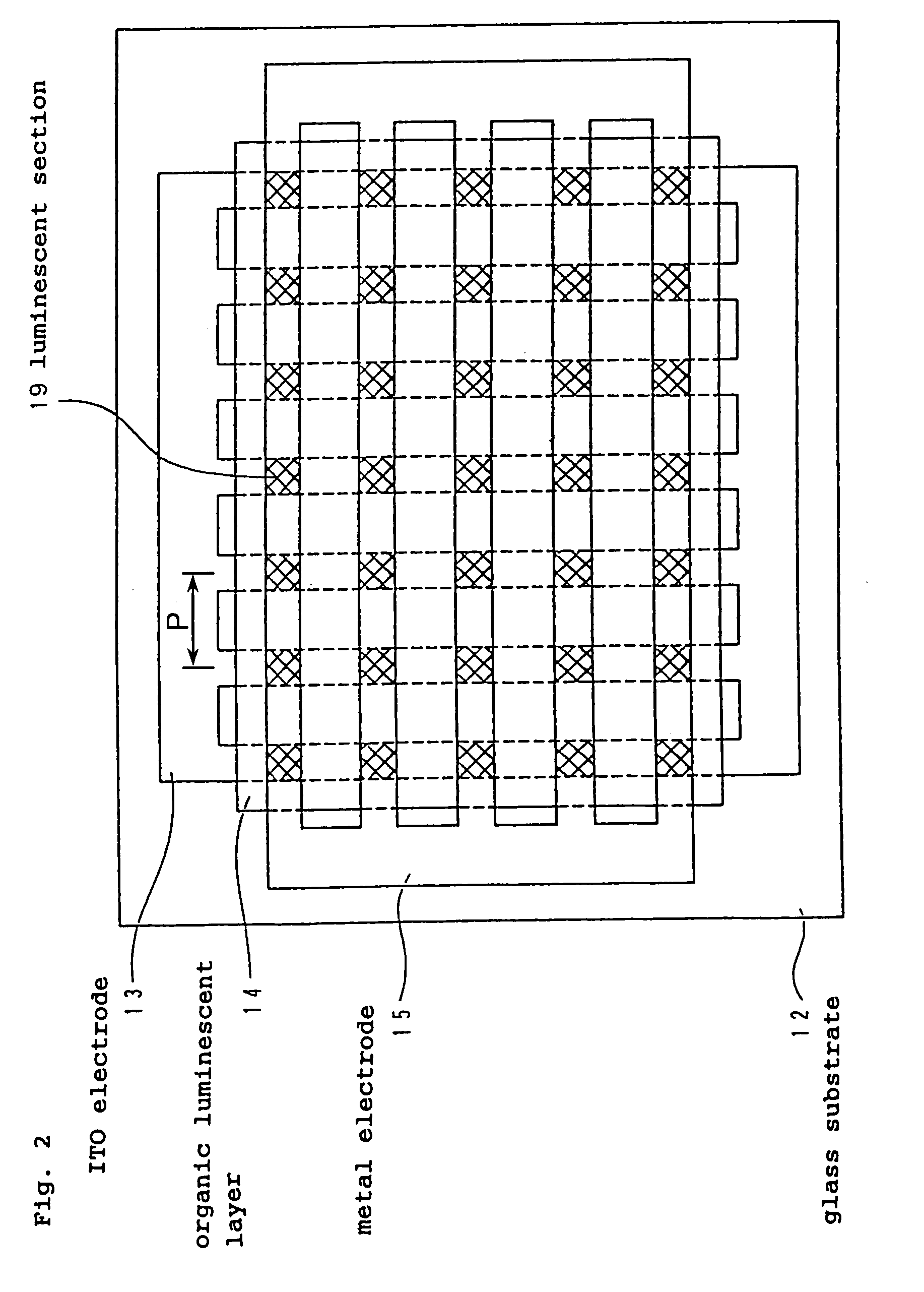
[0060]First, a first embodiment will be described based on FIGS. 1 and 2. FIG. 1 is a sectional view of a major optical system constituting a projection liquid crystal display device as a display device in accordance with this embodiment, and FIG. 2 is a plan view showing the structure of a light source that includes organic EL elements. Although only 7 pieces across and 5 pieces down of luminescent sections 20 that include the organic EL elements are depicted to facilitate viewing in FIG. 2, the actual array includes many more luminescent sections.

[0061]In the structure shown in FIG. 1, a liquid crystal display element 11R for displaying a red-component image, a liquid crystal display element 11G for displaying a green-component image, and a liquid crystal display element 11B for displaying a blue-component image are disposed opposite to the corresponding faces of a dichroic prism 16.

[0062]A red EL light source 10R that includes red organic EL elements, which are two-dimensionally ...

second embodiment

[0075]Next, a display device (projection liquid crystal display device) in accordance with the present invention will be described with reference to FIG. 4 and FIGS. 5A to 5D. FIG. 4 is a sectional view showing a major optical system constituting a projection liquid crystal display device, and FIGS. 5A to 5D are diagrams which show waveforms of pulse currents applied to organic EL elements as light sources to cause light emission.

[0076]The structure of the optical system shown in FIG. 4 is substantially the same as that of the display device in the first embodiment. A liquid crystal display element 21R for displaying a red-component image, a liquid crystal display element 21G for displaying a green-component image, and a liquid crystal display element 211B for displaying a blue-component image are disposed opposite to the corresponding faces of a dichroic prism 22. A red organic EL element 20R for emitting light at a wavelength in the red range is disposed at the rear of the liquid ...

fourth embodiment

[0092]A display device in accordance with the present invention will be described with reference to FIG. 8. The display device in this embodiment is a head-up display in which an image of a liquid crystal element is superimposed on a forward view by a combiner provided on a windshield of a car, and FIG. 8 is a sectional view showing a major optical system thereof. The display device in the embodiment displays a green image only.

[0093]A liquid crystal display element 21G is illuminated by an organic EL element 20G for emitting green light which is pulse-operated by a pulse current supply source 25G. An image displayed in the liquid crystal display element 21G is superimposed on a forward view 45 by an optical system including a relay lens 40, a mirror 41, and a concave holographic combiner 42 and appears in the space in front of the holographic combiner.

[0094]The organic EL element 20G is provided with a micro-resonator in the structure of a luminescent layer thereof, and can emit li...


PUM

PropertyMeasurementUnit
luminanceaaaaaaaaaa
wavelengthaaaaaaaaaa

Abstract

The invention provides electroluminescent (EL) elements, such that a red EL light source, a green EL light source and a blue EL light source emit red color light, green color light, and blue color light, respectively, and are disposed at the rear of liquid crystal display elements. Each EL light source includes an organic EL element in which an organic thin film emits light. Each EL light source has a structure in which an organic luminescent layer is sandwiched between an indium tin oxide (ITO) electrode and a metal electrode which have striped patterns which are orthogonal to each other, and sections (luminescent sections) at which the striped patterns of the ITO electrode and the metal electrode intersect with each other emit light. The luminescent sections are arrayed two-dimensionally on a glass substrate and illuminate the entire display area of the liquid crystal display element.

Description

BACKGROUND OF THE INVENTION[0001]1. Field of the Invention[0002]The present invention relates to a light source for illuminating a display element and to a method for operating the same, and also relates to a display device or a display apparatus for performing display by illuminating a display element by the light source.[0003]2. Description of Related Art[0004]With respect to a technique for reducing the size of a projection liquid crystal display device which performs display by enlarging and projecting an image of a liquid crystal display element, Japanese Unexamined Patent Application Publication No. 51-119243 can be referred to. This publication discloses the structure of a display device in which a liquid crystal display element is illuminated by a planar light source, such as an electroluminescent element (hereinafter referred to as “EL element”), and an image displayed in the liquid crystal display element is enlarged and projected onto a screen by a lens.[0005]Recently, wi...

Claims


Application Information

Patent Timeline
Patent Type & Authority Patents(United States)
IPC IPC(8): G09G3/30G02F1/13357H01L27/32H04N5/74H04N9/31H05B44/00
CPCG02B27/01G02F1/133603G03B21/00G03B33/06G03B33/12H01L27/3232H04N9/3105H04N9/3155H04N9/3164H04N9/3197G02B5/32G02B2027/0112G02B2027/0118G02F2001/133622G02F2202/02H01L27/3211H01L27/3281H04N5/7441G03B21/006G02F1/133622H10K59/35H10K59/50H10K59/17
Inventor YOKOYAMA, OSAMUMIYASHITA, SATORUSHIMODA, TATSUYATAGA, YASUNORITOKITO, SHIZUONODA, KOJI
Owner SEIKO EPSON CORP
Why Eureka
Try Eureka