
Apparatus for and method of recording optically scanned image

Inactive Publication Date: 2007-04-17
FUJIFILM CORP +1
View PDF4 Cites 0 Cited by
  • Summary
  • Abstract
  • Description
  • Claims
  • Application Information

AI Technical Summary

Benefits of technology

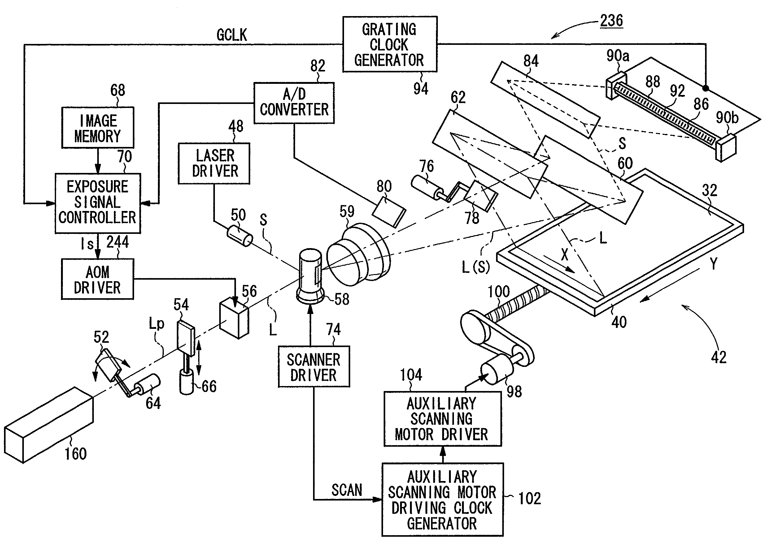
[0008]It is therefore an object of the present invention to provide an apparatus for and a method of recording an optically scanned image by appropriately controlling the intensity of a light signal to achieve both a desired image density or plate wear resistance and a high level of image quality even when small images are recorded.
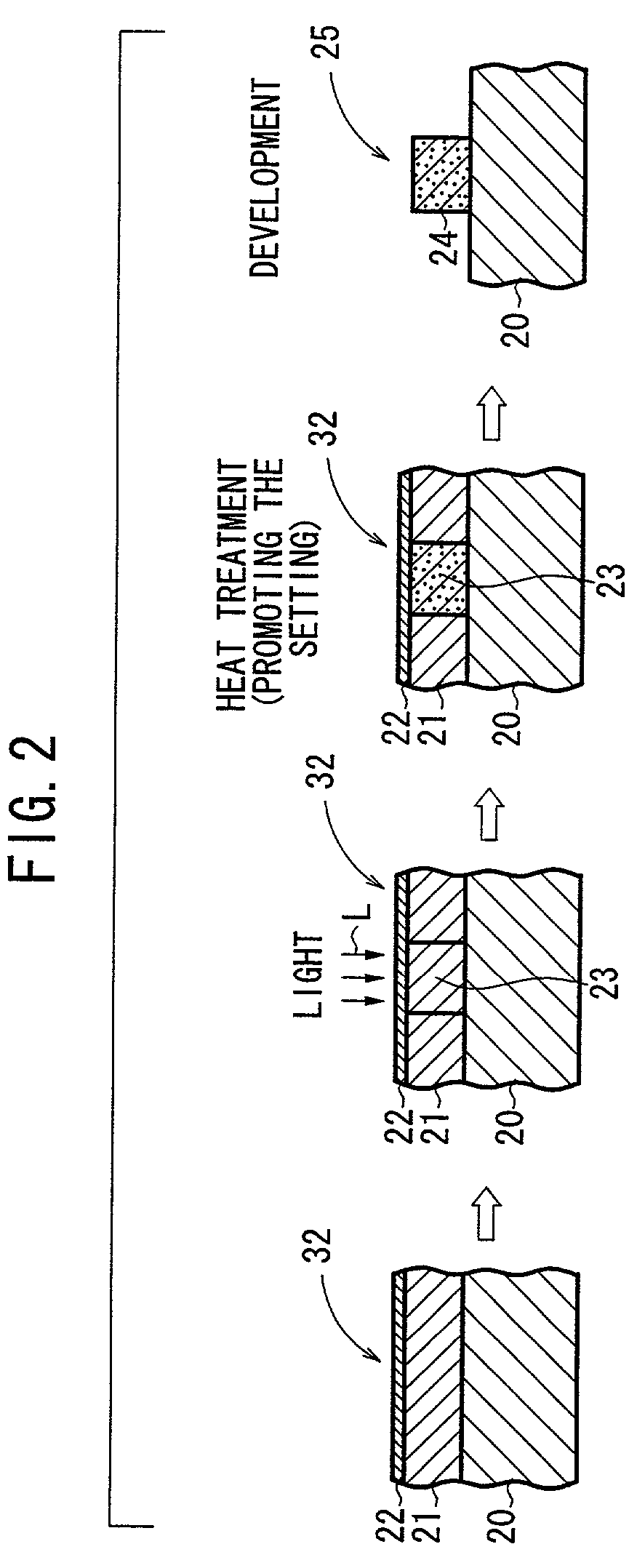
[0009]Another object of the present invention is to provide an apparatus for and a method of recording an optically scanned image on a photosensitive medium which has a photosensitive layer disposed on a support base and having portions turned into an image upon exposure to light, to achieve a sufficient level of plate wear resistance at highlight areas of the image recorded on the photosensitive medium and also to suppress the generation of image irregularities in the image.
[0010]Still another object of the present invention is to provide an apparatus for and a method of recording an optically scanned image on a photopolymer plate for printing applications by controlling an amount of exposure to light in view of photosensitive characteristics of the photopolymer plate thereby to achieve an optimum level of image quality and printing quality.
[0012]In the present invention, the light signal with the overshoot generated on the positive-going edge by the overshoot producing means is applied to scan the photosensitive medium by the recording light source to record an area gradation image on the photosensitive medium. Therefore, even when a small image is recorded on the photosensitive medium, a desired image density or a desired level of plate wear resistance can be achieved by the overshoot. When a large image is recorded, the photosensitive medium is scanned primarily by a flat portion of the light signal after the overshoot, so that the photosensitive medium is prevented from being overly scanned and the image recorded thereon has a high level of image quality.
[0014]If the photosensitive medium comprises a printing plate, then the wear resistance thereof is improved. If the photosensitive medium comprises a film, then a desired image density can be achieved thereby.
[0015]The recording light source comprises a semiconductor laser. The semiconductor laser used as the recording light source allows the overshoot to be generated easily with an electric circuit.

Problems solved by technology

With the exposure output recorded at the constant magnitude, however, depending on the photosensitivity characteristics of the photosensitive medium, a desired image density may not be achieved, i.e., a highlight jump may occur, when a small image of several pixels making up a highlight halftone dot is recorded on the photosensitive medium.
Photosensitive printing plate mediums such as photopolymer plates also suffer a problem in that their desired wear resistance cannot be obtained when they record small images by exposure to light.
The increased exposure power of the light signal is effective in increasing the wear resistance of the photosensitive medium, but tends to cause other problems of poor image quality including greater image irregularities in a large screen tint image due to an excessive amount of exposure to light, blurs on halftone dot edges, and increases in the width of thin lines.

Method used


Image

  • Apparatus for and method of recording optically scanned image
  • Apparatus for and method of recording optically scanned image
  • Apparatus for and method of recording optically scanned image

Examples


Embodiment Construction

[0032]Like or corresponding parts are denoted by like or corresponding reference characters throughout views.

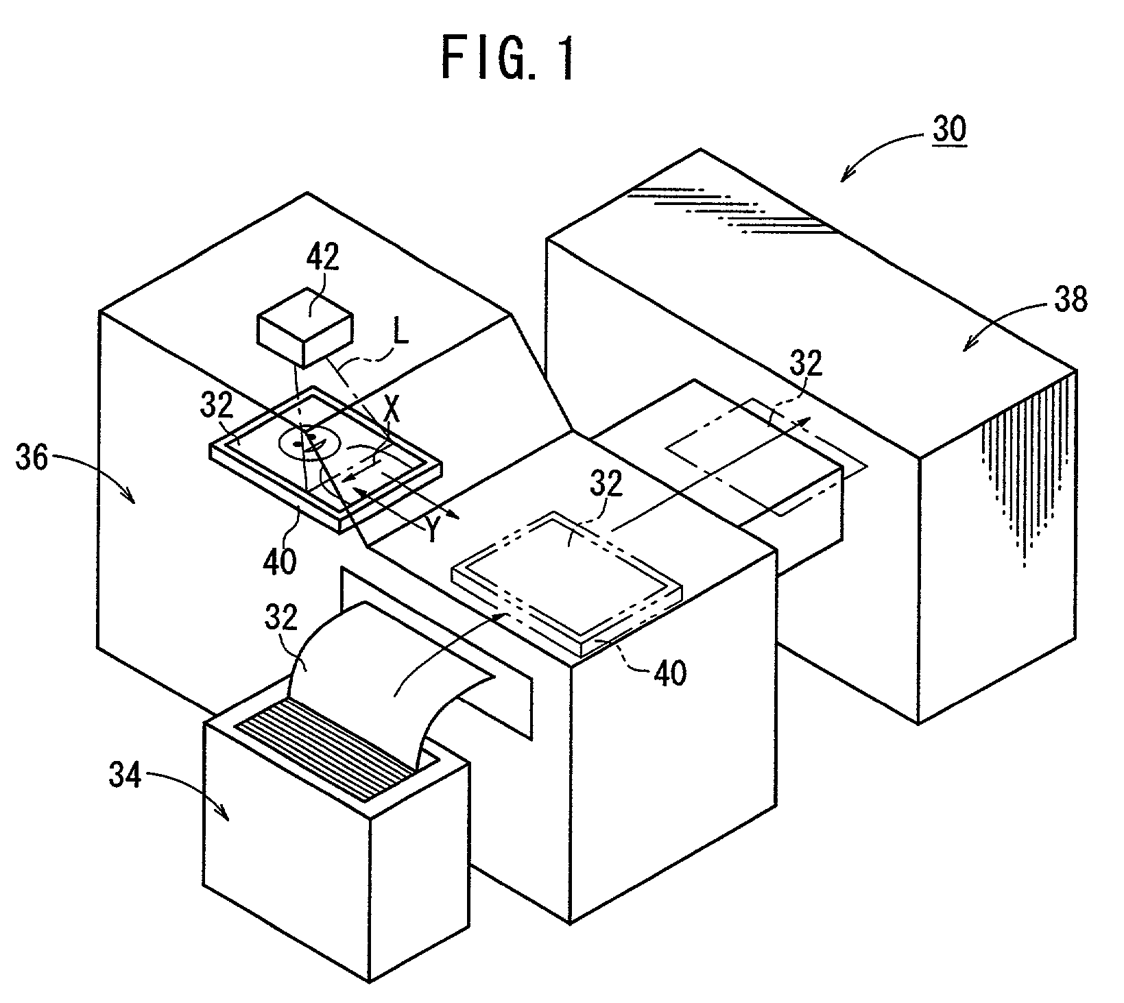
[0033]FIG. 1 shows in perspective a printing plate producing system 30 which incorporates an apparatus for and a method of recording an optically scanned image according to the present invention. The printing plate producing system 30 is a CTP (Computer To Plate) system for producing a printing plate on which an image for generating a printed material is recorded, directly from digital image data without using a film.

[0034]As shown in FIG. 1, the printing plate producing system basically comprises a plate supplying device 34 for supplying an unexposed photosensitive medium 32, an optically scanned image recording apparatus 36 for scanning an unexposed photosensitive medium 32 with a light signal L modulated by an image signal to record an image on the photosensitive medium 32, and a developing device 38 for developing the image recorded on the photosensitive medium 32.

[0035]T...


PUM


Abstract

An image signal with an overshoot is generated on a positive-going edge of an input image signal with an overshoot producing unit. Then, a light signal with an overshoot is outputted from a recording light source in response to the image signal with the overshoot supplied from the overshoot producing unit. The light signal outputted from the recording light source is applied to scan a photosensitive medium to record an area gradation image on the photosensitive medium.

Description

BACKGROUND OF THE INVENTION[0001]1. Field of the Invention[0002]The present invention relates to an apparatus for and a method of recording an image on a photosensitive medium by exposing the photosensitive medium to a light signal by scanning the photosensitive medium with the light signal, and more particularly to an apparatus for and a method of recording an image with a light signal on a photopolymer plate for use in printing applications.[0003]2. Description of the Related Art[0004]There are known optical scanning image recording apparatus for recording an area gradation image with a light signal on a photosensitive medium such as a photographic film according to a scanning exposure process. In such optical scanning image recording apparatus, the exposure power or exposure energy density of the light signal is recorded on the photosensitive medium at a certain constant magnitude regardless of the size of the image recorded on the photosensitive medium.[0005]With the exposure ou...

Claims


Application Information

Patent Timeline
IPC IPC(8): B41J2/47B41J2/44B41C1/00G02B26/10G03B27/32G03F3/08G03F7/20H01S5/0683H04N1/036H04N1/113H04N1/23H04N1/40
CPCG03F7/2055H04N1/40037
Inventor SUMI, KATSUTO
Owner FUJIFILM CORP
Learn More