Display module and display unit

a display module and display module technology, applied in the direction of identification means, instruments, optics, etc., can solve the problems of poor serviceability, unsatisfactory shielding against emi (electromagnetic interference), and the connection or breakage of the flexible printed circuit is not perfect, so as to achieve convenient removal, satisfactory shielding against emi, and compact

Inactive Publication Date: 2007-04-17
JAPAN DISPLAY WEST
View PDF10 Cites 21 Cited by
  • Summary
  • Abstract
  • Description
  • Claims
  • Application Information

AI Technical Summary

Benefits of technology

[0010]An object of the present invention is to provide a display module to which a flexible printed circuit can be fixed so as to be easily removable therefrom and in which satisfactory shielding against EMI is achieved. Another object of the present invention is to provide a display unit that is made compact by minimizing dead space. Still another object of the present invention is to provide a display module suitable for minimization of display units.
[0016]The display module may be provided with a support frame that supports the display panel and that has wall surfaces formed along the inner surfaces of the notches. This helps prevent entry of dust through the notches, and thus helps prevent degradation of display quality. Moreover, this structure for preventing entry of dust is used also for the positioning of the front frame, contributing to simplification of the structure.
[0018]With this structure, it is possible to provide a compact display unit of which the frame portion surrounding the display area has a small area.
[0021]With these structures, it is possible to easily fit the flexible printed circuit to the rear casing, to prevent breakage of the flexible printed circuit during the manufacture or maintenance of the display module, to enhance assembly efficiency, and to reduce the space required to house the flexible printed circuit. Moreover, also at the time of maintenance, it is possible to easily detach the flexible printed circuit, leading to better serviceability.
[0023]With this structure, it is possible to realize the fixing means inexpensively, and to easily attach and detach the protective plate.
[0028]With these structures, it is possible to ground, by way of the rear casing, the metal film or the like provided in the flexible printed circuit for shielding against EMI This makes it possible to achieve shielding against EMI with a simple structure and at low cost.

Problems solved by technology

As a result, when the display module is handled, the flexible printed circuit 109 is prone to be caught at some edge or other, leading to imperfect connection or breakage of the flexible printed circuit 109.
This leads to poor serviceability.
Furthermore, with conventional flexible printed circuits, satisfactory shielding against EMI (electromagnetic interference) has not been achieved.

Method used


Image

  • Display module and display unit
  • Display module and display unit
  • Display module and display unit

Examples


Embodiment Construction

[0045]Hereinafter, embodiments of the present invention will be described with reference to the drawings.

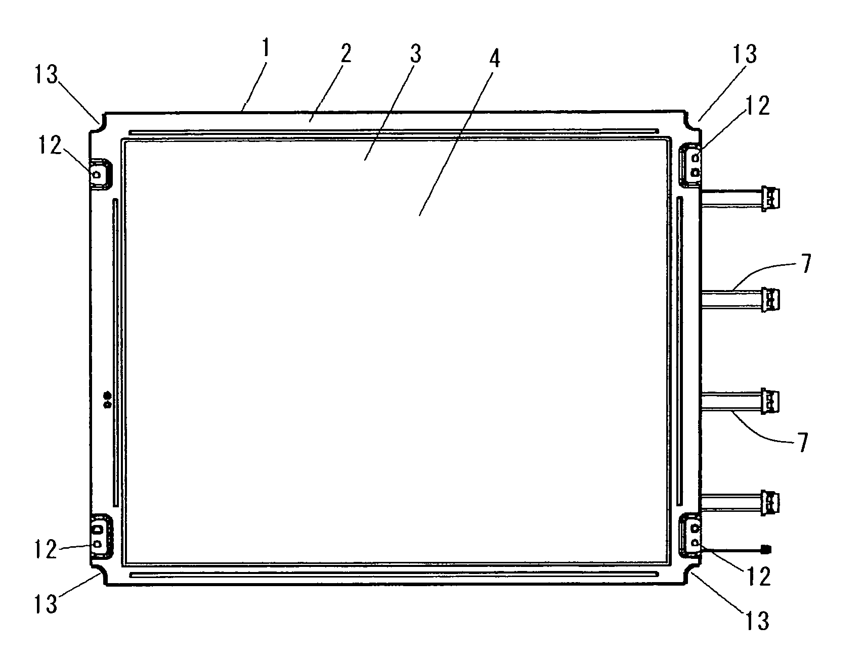
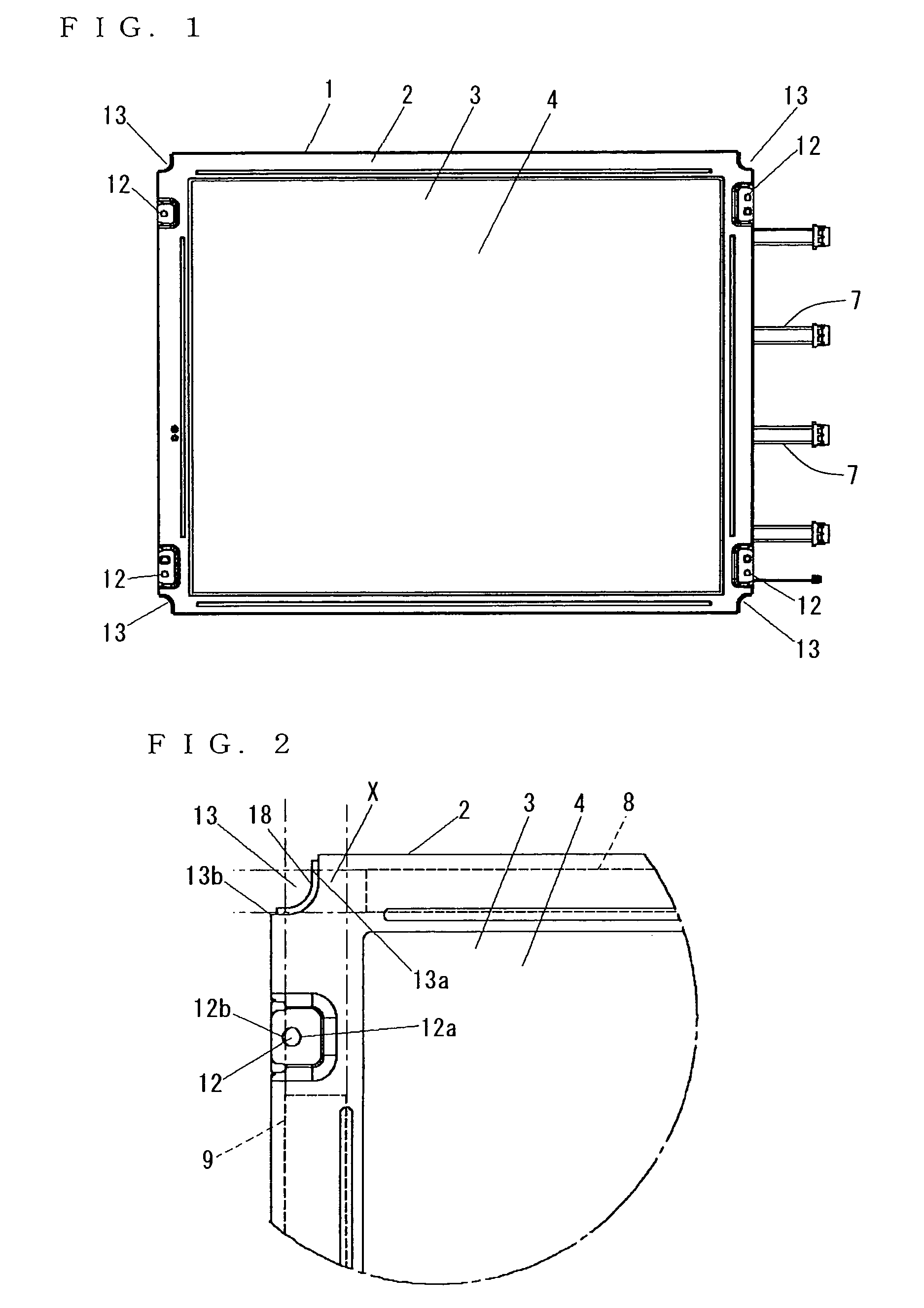
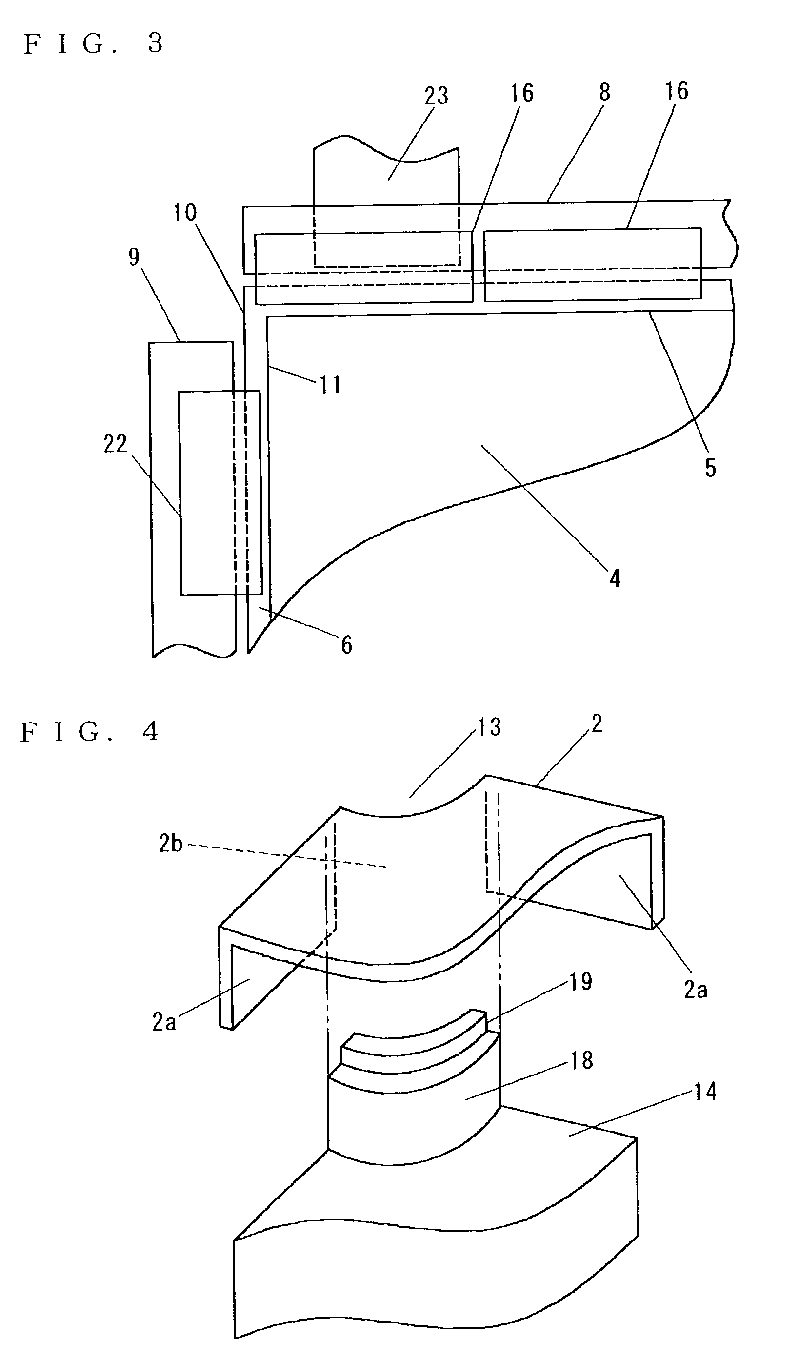
[0046]FIG. 1 is a plan view of a liquid crystal display module 1 embodying the invention, FIG. 2 is an enlarged plan view of a principal portion of FIG. 1, FIG. 3 is a plan view of a principal portion of the display module 1, FIG. 4 is a perspective view of a principal portion of the display module 1, FIG. 5 is a perspective view, as seen from behind, of a principal portion of the display module 1, FIG. 6 is a plan view of a display unit incorporating the display module 1, with its upper casing removed, FIG. 7 is a rear perspective view of another display module embodying the invention, FIG. 8 is a front view of the display module, with its front frame removed, FIG. 9 is a side view of the display module, and FIG. 10 is an enlarged outline view of part B shown in FIG. 9.

[0047]The liquid crystal display module 1 is provided with a picture-frame-shaped front frame 2 that surrounds ...


PUM

PropertyMeasurementUnit
radiusaaaaaaaaaa
widthaaaaaaaaaa
areaaaaaaaaaaa

Abstract

In a display module having a picture-frame-shaped front frame, notches are formed at both ends of one side edge thereof so as to penetrate from the front surface to the rear surface thereof. This helps realize a compact display unit. Moreover, a metal film or the like is formed on a flexible printed circuit used in the display module, and the flexible printed circuit is fixed to a metal rear casing with a detachable protective plate. This helps realize a display module that permits easy attachment and detachment of a flexible printed circuit and in which sufficient shielding against EMI (the metal film is grounded via the rear casing) is achieved.

Description

TECHNICAL FIELD[0001]The present invention relates to a display module and a display unit incorporating it, and to a display module employing a direct-lit backlight.BACKGROUND ART[0002]Conventionally, color television monitors typically employ CRTs (cathode ray tubes). In recent years, however, television monitors employing liquid crystal displays have been put into practical use thanks to slimming-down and low power consumption achieved in modern display modules. The mainstream of display modules for use in television monitors and large-screen monitors is the TFT (thin-film transistor) LCDs (liquid crystal displays). In a TFT LCD, on one of the glass substrates constituting a display panel, scanning lines and signals lines, both connected to TFTs, are formed in a matrix-like formation, and input terminals for those scanning and signal lines are arranged in an edge portion of the glass substrate. In general, there are more signal lines than there are scanning lines, and therefore th...

Claims


Application Information

Patent Timeline
Patent Type & Authority Patents(United States)
IPC IPC(8): G02F1/1333G02F1/13G02F1/1345G06F1/16G09F9/00H05K1/02H05K9/00
CPCG02F1/133308G06F1/1601G02F1/133305G02F1/133602G02F1/13452G02F2001/133322G02F2001/133334G06F2200/1612H01J2211/446G02F1/133322G02F1/133334G02F1/1333
Inventor NISHIO, TOSHIYAYAMANE, SEIJI
Owner JAPAN DISPLAY WEST
Why Eureka
Try Eureka