Reflectance surface analyzer

a surface analyzer and reflectance technology, applied in the field of optical instruments, can solve problems such as inefficiency, and achieve the effect of efficient gathering and detection of incoming signals

Active Publication Date: 2007-04-17
KLA TENCOR TECH CORP
View PDF24 Cites 14 Cited by
  • Summary
  • Abstract
  • Description
  • Claims
  • Application Information

AI Technical Summary

Benefits of technology

[0005]As more is demanded from units such as hard disks and other products with which the present instrumentation is used, more is required from the instrumentation since the instruments themselves must be capable of detecting more information and information of a more sensitive nature. Current instrumentation is very effective in showing gradual surface variations such as waviness, gradual changes in thickness or optical characteristics in a thin film layer. Yet greater sensitivity is required in connection with the detection of surface scratches as well as the detection of smaller scattering events such as those produced by small particles. In this respect, improving techniques for the detection of scattered light by Surface Reflectance Analyzers is recognized as a mechanism to enhance the detection of surface scratches as well as other scattering events such as small particles at the surface or in the uppermost layer. This invention permits the acquisition of greater amounts of useful data from the surface or layer under examination than has heretofore been possible through improvements in, among other segments, the detection system of the instrument. This also includes the capability of determining the directionality and the spatial distribution of scattered light from the surface or layer under examination. Also to assure the dependability of manufactured instrumentation, certain optical and structural elements have been incorporated into the units, such as compensators and other assemblies that permit flexibility in positioning components. These elements enable fine tuning as well as adjustments in the final product so that each manufactured unit will regularly be of the highest quality notwithstanding slight variations that typically exist from like parts as would normally get incorporated into successive units of equipment during manufacture.
[0006]According to Rayleigh's scattering theory, scattering cross section of a small spherical particle of radius a, by photons of wavelength λ, provided a<<λ, is proportional to:a6 / λ4Therefore in order to detect smaller scattering events such as those produced by small particles, lasers with smaller wavelengths are beneficial. Additionally, efficient collection of scattered light from the surface being measured is essential. Currently an integrating sphere is used, in which scattered light is collected using a spherical cavity with a diffused white surface on the inside. The sphere is positioned above but close to the surface where the laser beam is focused to strike. Any scattering event on the surface being examined produces scattered light that is captured by the cavity. Within the cavity, the light bounces off the inside walls many times and finally is picked up at a detector located at the other end of the cavity. A problem with this type of integrating cavity is that they are not very efficient. In order to detect as much of the scattered light as possible or in order to act with greater efficiency Surface Reflectance Analyzers in accordance with this invention use a newly designed cavity that is much more efficient and is thus more effective in detecting scattering light events or incidents at the surface under examination. The novel cavity in accordance with this invention has a mirror or mirror-like finish on its inside surface walls and is more efficient in gathering and detecting data.
[0008]It is a further object of this invention to describe a novel integrating cavity with an elliptical configuration which efficiently gathers and detects incoming signals of surface faults.
[0009]It is a further object of this invention to describe an improved Surface Reflectance Analyzer employing a stabilized laser of reduced frequency which will enhance the detection of surface scatter and surface information.

Problems solved by technology

A problem with this type of integrating cavity is that they are not very efficient.

Method used


Image

  • Reflectance surface analyzer
  • Reflectance surface analyzer
  • Reflectance surface analyzer

Examples


Embodiment Construction

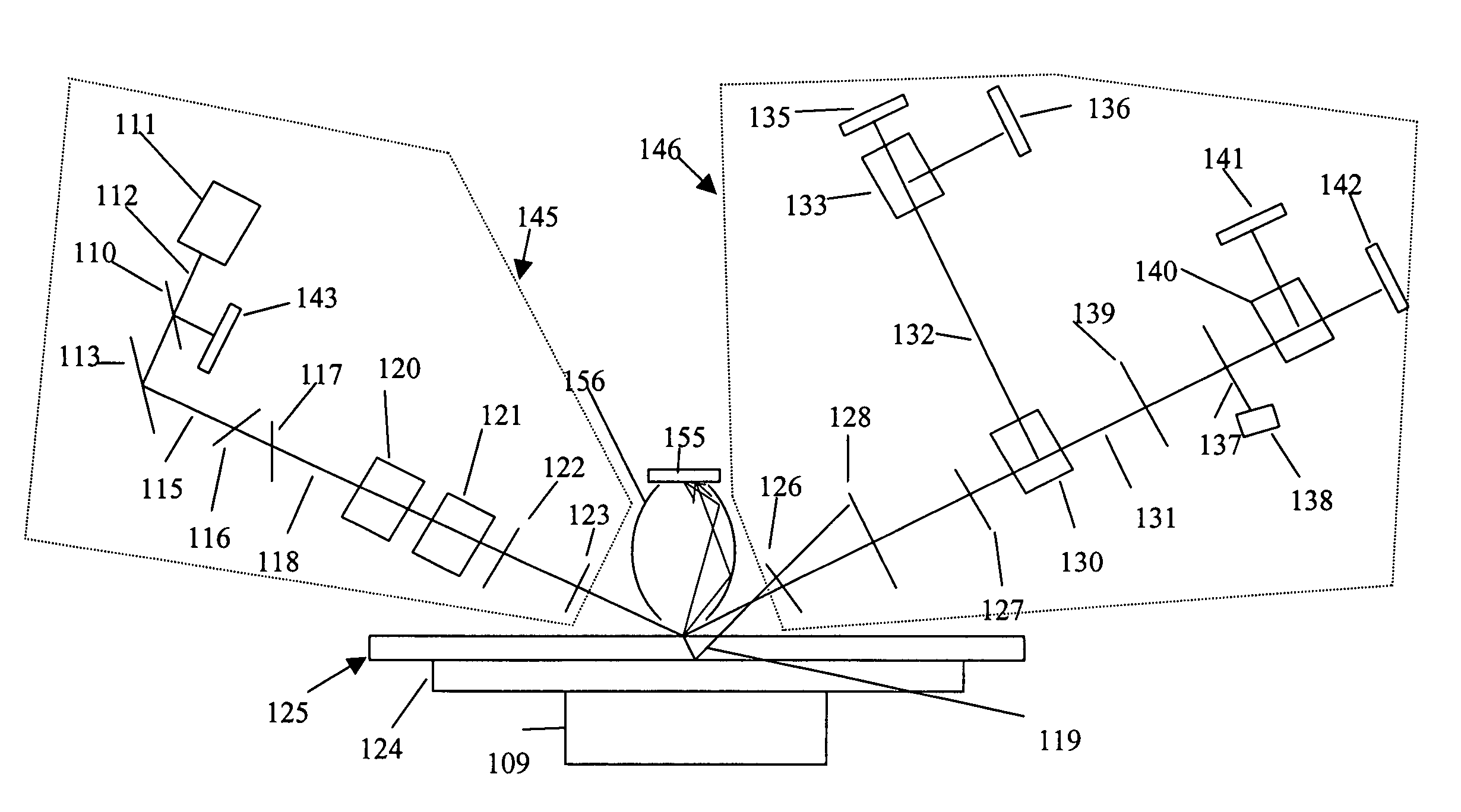
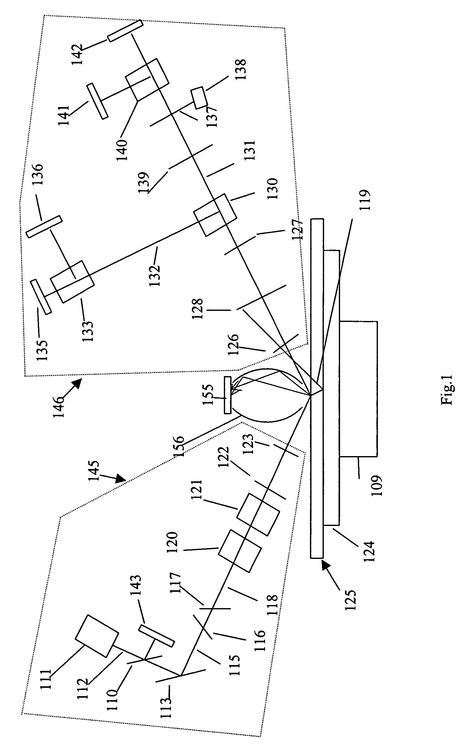
[0016]Referring now to FIG. 1, a light source 111 directs a beam illustrated as 112 through a beamsplitter 110 and a detector 143 to monitor the laser power. The beam is then directed onto a mirror 113 where it is reflected as beam 115 (different numbers are being used in connection with different sections of the beam in order to simplify understanding of the drawings). The mirror is positioned on a mirror mount to steer the beam so that it eventually strikes the surface under examination at an angle of approximately sixty degrees. The mirror 113 permits use of a folded optical system that has the effect of shortening its length. However, if the overall length of the system is not important, the mirror could be omitted. The angle of incident although not unique, is chosen to fall within the range of 50 & 80 degrees from the normal. The beam next passes through filters 116 and 117. These are neutral density filters placed at an angle other than normal to the beam and in an opposite s...


PUM

PropertyMeasurementUnit
intensity stabilized wavelengthaaaaaaaaaa
wavelengthaaaaaaaaaa
angleaaaaaaaaaa

Abstract

There is described an improved Surface Reflectance Instrument which achieves more complete detection of surface defects in the nature of small particles. One of the improvements is the use of an elliptical integrated cavity with internal surface mirrors, and another the use of a position sensing diode as the detector for the scattered light. Other improvements and the use of a stable laser at a particular wavelength resulting in greater detection are also described.

Description

BACKGROUND OF THE INVENTION[0001]This invention relates to optical instrumentation and to the optical measurement of surface qualities and characteristics. In particular there exists today instruments to study surfaces by reflective techniques. These provide measurements of various characteristics and / or qualities of surfaces and of thin film layers that are at least partially light transmissive when deposited on a substrate. A surface for measurement may comprise the surface of a hard disk or a computer memory which initially may comprise a metallic or glass support layer and deposited coating layers of magnetic media with a final layer of carbon and a lubricant layer deposited onto the surface of the disk on the carbon layer.[0002]One form of instrument for optical diagnostics is known as a reflection ellipsometer. Another is known as a polarization-modulated ellipsometer. However, these units are relatively slow and not useful in situations demanding real time measurements of a s...

Claims


Application Information

Patent Timeline
Patent Type & Authority Patents(United States)
IPC IPC(8): G01N21/88G01N21/21
CPCG01N21/211
Inventor VURENS, GERARD H.KHAZENI, KASRA
Owner KLA TENCOR TECH CORP
Why Eureka
Try Eureka