Radio receiver

a radio receiver and receiver technology, applied in the field of radio receivers, can solve the problems of increasing the maintenance cost of the communication service, not being able to have an external vacuum pump, and not being able to achieve the effect of reducing the maintenance cos

Inactive Publication Date: 2007-04-17
NEC CORP
View PDF17 Cites 71 Cited by
  • Summary
  • Abstract
  • Description
  • Claims
  • Application Information

AI Technical Summary

Benefits of technology

[0009]This invention is invented considering the above problems and is intended to provide a radio receiver that does not need the maintenance work to evacuate air by connecting the vacuum container to the vacuum pump from outside, thereby allowing the reduction in maintenance cost.

Problems solved by technology

Thus, it is not desirable that the radio receiver has an external vacuum pump for evacuating always the interior of the vacuum container 55 since it becomes difficult to miniaturize and lighten.
This is not desirable since it increases the maintenance cost on the communication service.
Therefore, it is necessary for the interior of the vacuum container 55 to be evacuated periodically and the maintenance cost increase by that much.
As a result, it is necessary for the interior of the vacuum container 55 to be evacuated periodically after about 1000 hour operation and, therefore, the maintenance cost increase by that much.

Method used


Image

  • Radio receiver
  • Radio receiver
  • Radio receiver

Examples


first embodiment

[0032][First Embodiment]

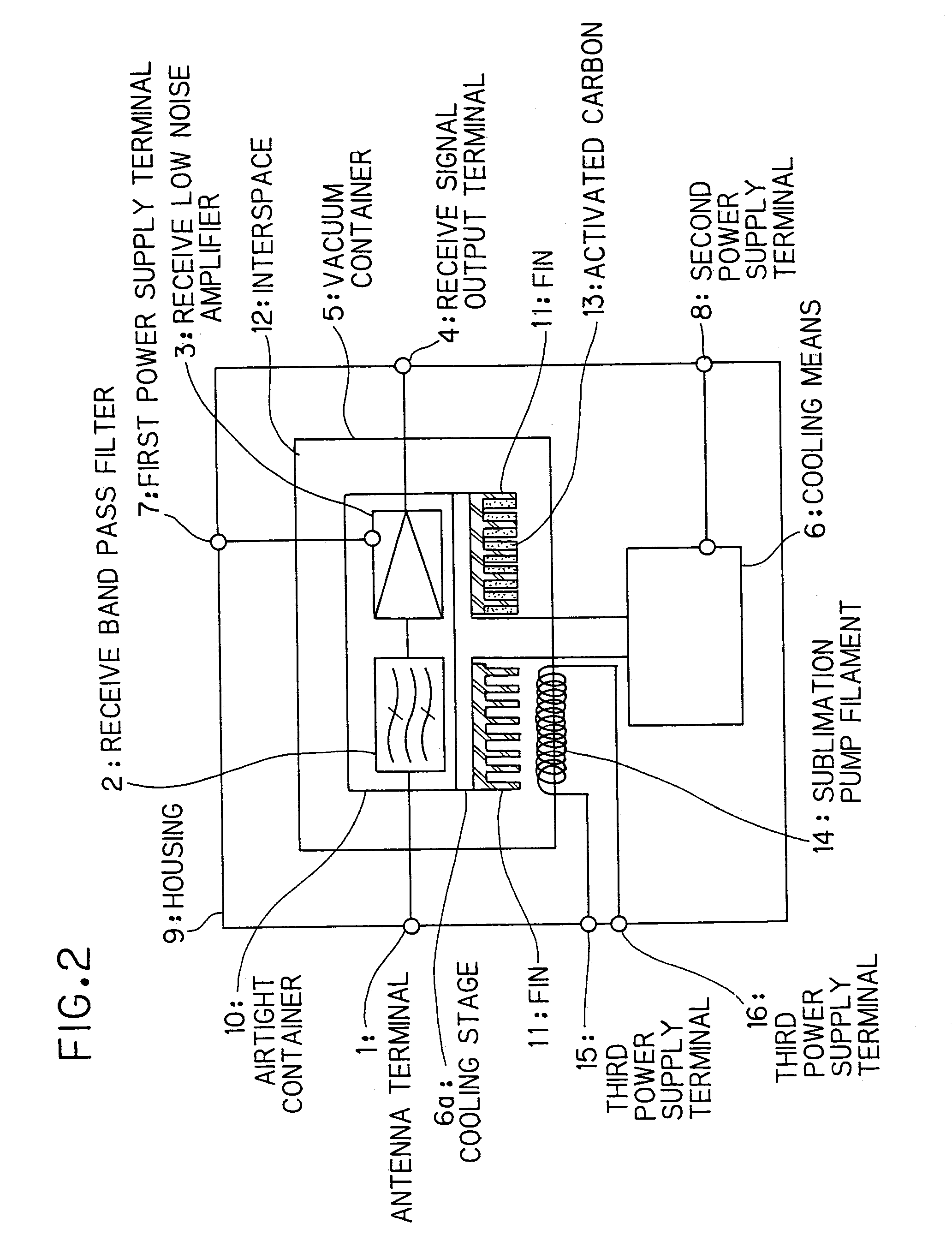
[0033]FIG. 2 is an illustration showing the composition of a radio receiver in the first preferred embodiment according to the invention.

[0034]The radio receiver in this embodiment is, as shown in FIG. 2, composed of an antenna terminal 1, a receive band pass filter 2 that selects a desired band signal from receive signal to be inputted, a receive low noise amplifier 3 that amplifies the output of the receive band pass filter 2 with low noise up to a desired level, a receive signal output terminal 4, an airtight container 10 that seals in vacuum the receive band pass filter 2 and the receive low noise amplifier 3, a vacuum container 5 that seals in vacuum the airtight container 10 such that an interspace 12 between the vacuum container 5 and the airtight container 10 forms a vacuum insulating space, a cooling means 6 that cools the interior of the vacuum container 5 through a cooling stage 6a, fins 11 provided beneath the cooling stage 6a, activated carbon 13...

second embodiment

[0050][Second Embodiment]

[0051]FIG. 3 is an illustration showing the composition of a radio receiver in the second preferred embodiment according to the invention. The difference of the radio receiver in the second embodiment from that in the first embodiment is that there are provided two vacuum insulating spaces.

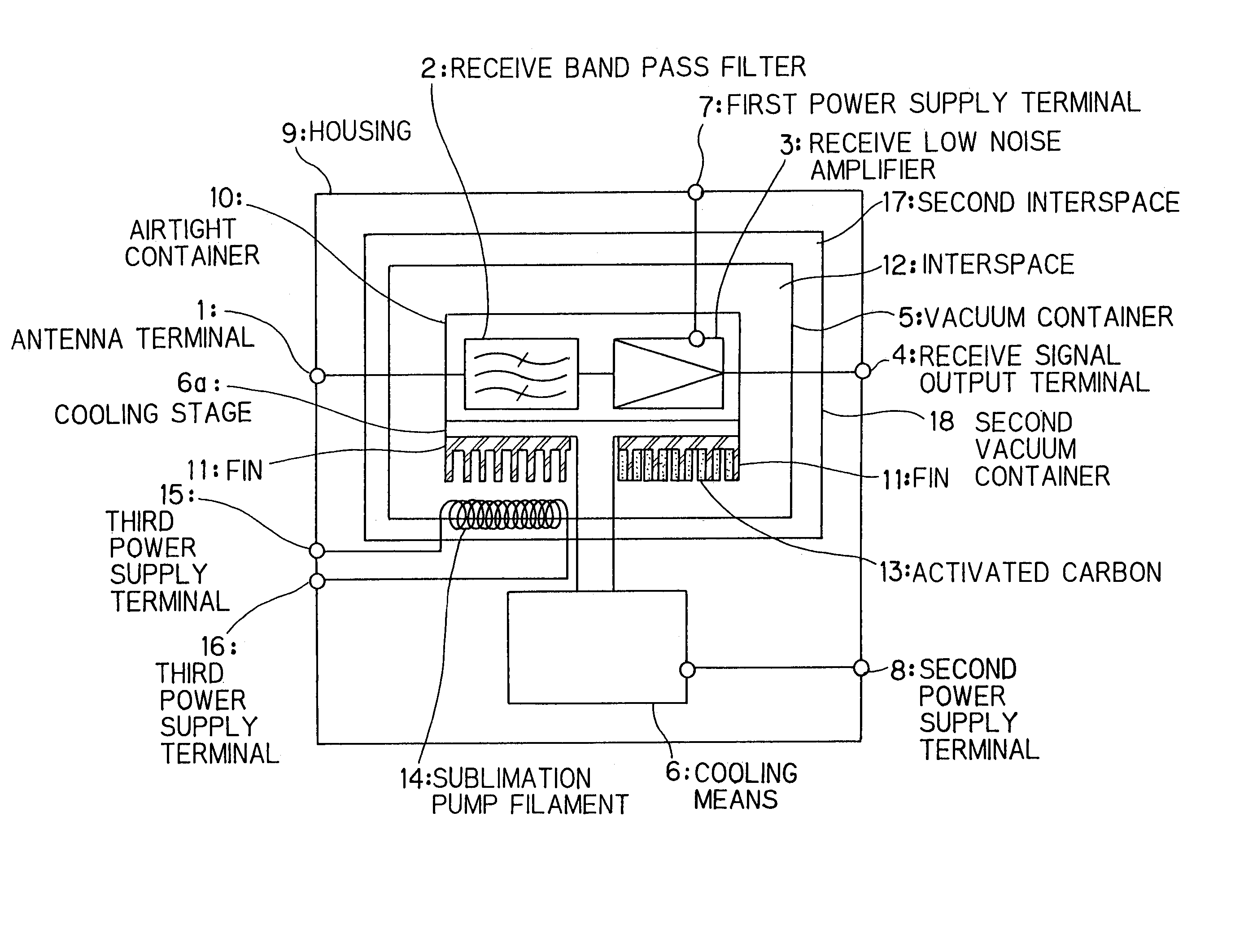
[0052]Namely, the radio receiver in the second embodiment includes, as shown in FIG. 3, a second vacuum container 18 that operates as outer sealing means to seal in vacuum the vacuum container 5 such that a second interspace 17 between the second vacuum container 18 and the vacuum container 5 forms a second vacuum insulating space. Material of the second vacuum container 18 that allows the second vacuum insulating space to be formed in the second interspace 17 between the second vacuum container 18 and the vacuum container 5 is of stainless alloys, aluminum alloys, FRP (fiberglass reinforced plastic) etc like the vacuum container 5. The degree of vacuum in the second vacuu...


PUM


Abstract

A radio receiver disclosed is composed of a signal processing part, which includes a receive band pass filter 2 and a receive low noise amplifier 3, to process receive signal and discharge gas with time, the signal processing part being cooled by the cooling means 6, wherein the radio receiver is provided with an airtight container 10 that operates as inner sealing means to seal the receive band pass filter 2 and the receive low noise amplifier 3 to retain the gas, and a vacuum container 5 that operates as outer sealing means to seal in vacuum the airtight container 10 such that an interspace 12 between that and the airtight container 10 forms a vacuum insulating space to insulate in vacuum the airtight container 10 from outside.

Description

TECHNICAL FIELD[0001]This invention relates to a radio receiver and, particularly, to a radio receiver that is applied to a base station radio device for mobile communication and satellite communication and that receives a desired signal while having its signal processing part cooled.BACKGROUND ART[0002]A conventional radio receiver, which is applied to base station radio device, is as shown in FIG. 1 composed of an antenna terminal 51, a receive band pass filter 52 that selects a desired band signal from receive signal to be inputted from the antenna terminal 51, a receive low noise amplifier 53 that amplifies the output of the receive band pass filter 52 with low noise up to a desired level, a receive signal output terminal 54 that outputs the receive signal amplified by the receive low noise amplifier 53, a vacuum container 55 that seals in vacuum the receive band pass filter 52 and the receive low noise amplifier 53, a cooling means 56 that cools the interior of the vacuum conta...

Claims


Application Information

Patent Timeline
Patent Type & Authority Patents(United States)
IPC IPC(8): H04M1/00H04B1/10H01L39/04H04B1/036H04B1/08H04B1/18
CPCH04B1/036H04B1/18
Inventor HATTORI, WATARU
Owner NEC CORP
Why Eureka
Try Eureka