Method and apparatus for aligning a pair of digital cameras forming a three dimensional image to compensate for a physical misalignment of cameras

a technology of digital cameras and three-dimensional images, applied in the field of digital camera systems, to achieve the effect of eliminating time and expense and very quickly performing alignmen

Inactive Publication Date: 2007-04-24
THE BOEING CO
View PDF7 Cites 59 Cited by
  • Summary
  • Abstract
  • Description
  • Claims
  • Application Information

AI Technical Summary

Benefits of technology

[0007]A principal advantage of the present invention is that since the digital images produced by each of the two digital cameras are electronically aligned, such alignment can be performed very quickly. It also becomes unnecessary to remove the cameras from their common mounting platform or from an aircraft or other vehicle to which they may be directly mounted on. This eliminates the time and expense associated with previous approaches for aligning digital images that involve the requirement of removing the entire mounting platform on which the cameras are mounted and transporting the platform to a laboratory environment where the alignment can be effected.
[0008]Further areas of applicability of the present invention will become apparent from the detailed description provided hereinafter. It should be understood that the detailed description and specific examples are intended for purposes of illustration only and are not intended to limited the scope of the invention.

Problems solved by technology

It also becomes unnecessary to remove the cameras from their common mounting platform or from an aircraft or other vehicle to which they may be directly mounted on.

Method used


Image

  • Method and apparatus for aligning a pair of digital cameras forming a three dimensional image to compensate for a physical misalignment of cameras
  • Method and apparatus for aligning a pair of digital cameras forming a three dimensional image to compensate for a physical misalignment of cameras
  • Method and apparatus for aligning a pair of digital cameras forming a three dimensional image to compensate for a physical misalignment of cameras

Examples


Embodiment Construction

[0013]The following description of the preferred embodiment(s) is merely exemplary in nature and is in no way intended to limit the invention, its application, or uses.

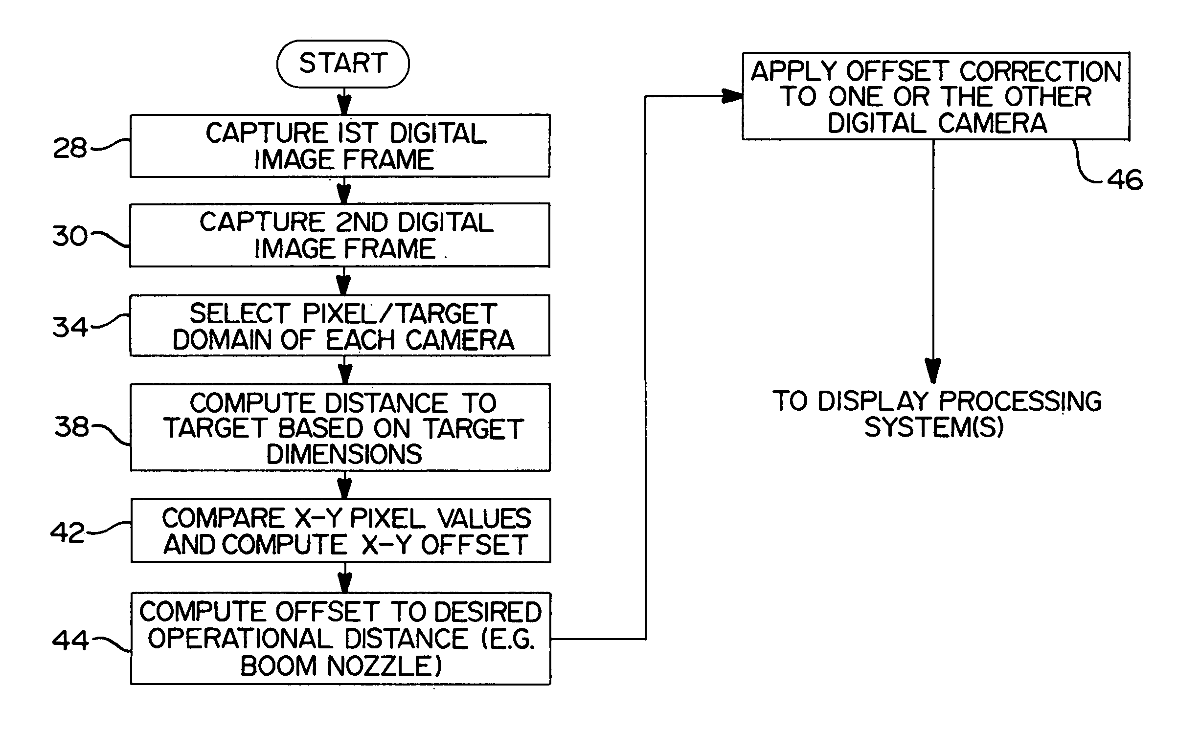
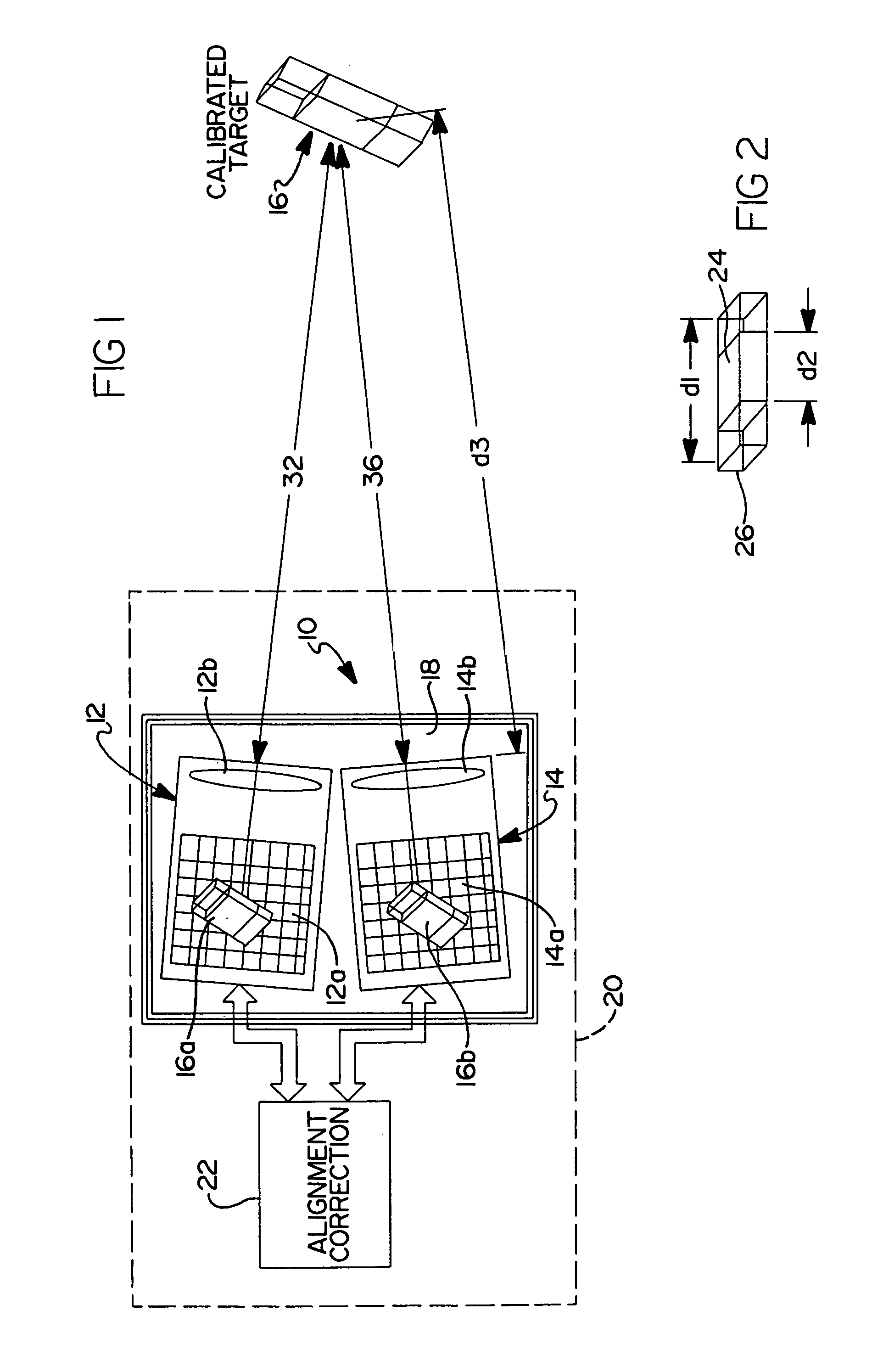
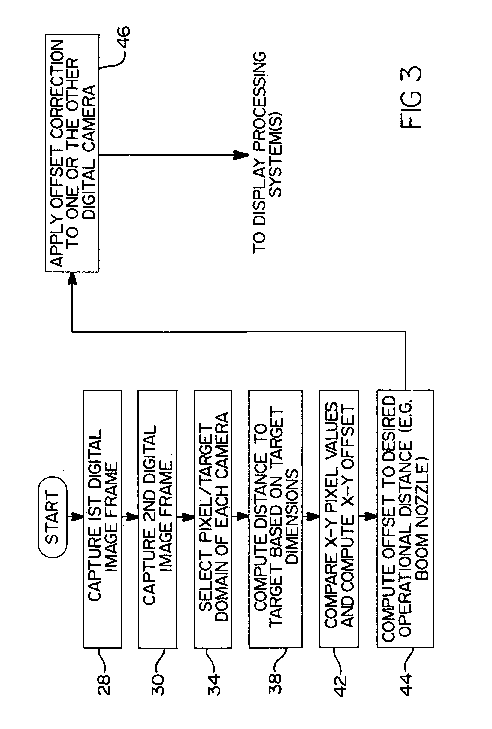
[0014]Referring to FIG. 1, there is shown a digital imaging system 10 in accordance with a preferred embodiment of the present invention for forming a composite, three dimensional digital image. System 10 includes a pair of digital cameras 12 and 14 which each are directed at a common target 16. The cameras 12 and 14 are also mounted on a platform 18 which is in turn supported on a different structure or a platform 20, such as possibly an aircraft, bus or other motor vehicle, ship, or even stationary support surface. Accordingly, while it will be appreciated that the present invention 10 will have particular utility with regard to use on mobile platforms, the invention is not so limited and may be used in connection with fixed (i.e., ground-based) support structures.

[0015]The imaging system 10 further includes an alig...


PUM


Abstract

An apparatus and method for detecting and correcting for physical misalignments of a pair of digital cameras creating a composite, three dimensional (3D) image of a target. The method involves using the distances from each of a pair of digital cameras to a target and determining correction offset values for one or the other of the images produced in the digital cameras to achieve pixel-to-pixel coincidence of the two images. The correction offset values are calculated and performed in real time and eliminate the need to physically remove a common platform on which the cameras are mounted from a mobile platform or other support structure, and to transport same to a laboratory environment for the needed calibration. Advantageously, the correction values are generated electronically and applied in real time as any misalignment between the cameras is sensed.

Description

FIELD OF THE INVENTION[0001]The present invention relates to digital camera systems, and more particularly to a method and apparatus for electronically altering the digital image being produced by one of a pair of digital cameras cooperatively forming a three dimensional image, to thereby account for misalignment between the two cameras.BACKGROUND OF THE INVENTION[0002]Present three dimensional (3D) imaging systems used in remote vision applications require very accurate physical alignment of the pair of cameras being used to form the 3D image. More particularly, very fine pixel-to-pixel coincidence is needed to accurately produce a three dimensional image from the two cameras. The ability to provide an accurate, three dimensional image is especially important in certain applications, such as with military refueling tanker aircraft. With refueling tanker aircraft, a 3D vision system must be capable of providing an accurate and clear 3D image to an operator monitoring the positioning...

Claims


Application Information

Patent Timeline
Patent Type & Authority Patents(United States)
IPC IPC(8): H04N13/00H04N13/239
CPCG03B35/08G06T7/002H04N13/0239H04N13/0246H04N13/0296G06T2207/10012G06T2207/30181H04N13/0003H04N2013/0081G06T7/85H04N13/246H04N13/296H04N13/10H04N13/239
Inventor THAL, GERMAN VONROBERTS, GREGORY A.
Owner THE BOEING CO
Why Eureka
Try Eureka