Projection objective, especially for microlithography, and method for adjusting a projection objective

Inactive Publication Date: 2007-04-24
CARL ZEISS SMT GMBH
View PDF13 Cites 61 Cited by
  • Summary
  • Abstract
  • Description
  • Claims
  • Application Information

AI Technical Summary

Benefits of technology

[0012]It is one object of the invention to provide a projection objective and a suitable method for adjusting proje

Problems solved by technology

In the case of air systems, this reduces in proportion to 1/NA2, so that with high-aperture projection objec

Method used


Image

  • Projection objective, especially for microlithography, and method for adjusting a projection objective
  • Projection objective, especially for microlithography, and method for adjusting a projection objective
  • Projection objective, especially for microlithography, and method for adjusting a projection objective

Examples


Embodiment Construction

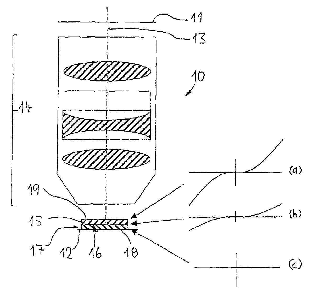
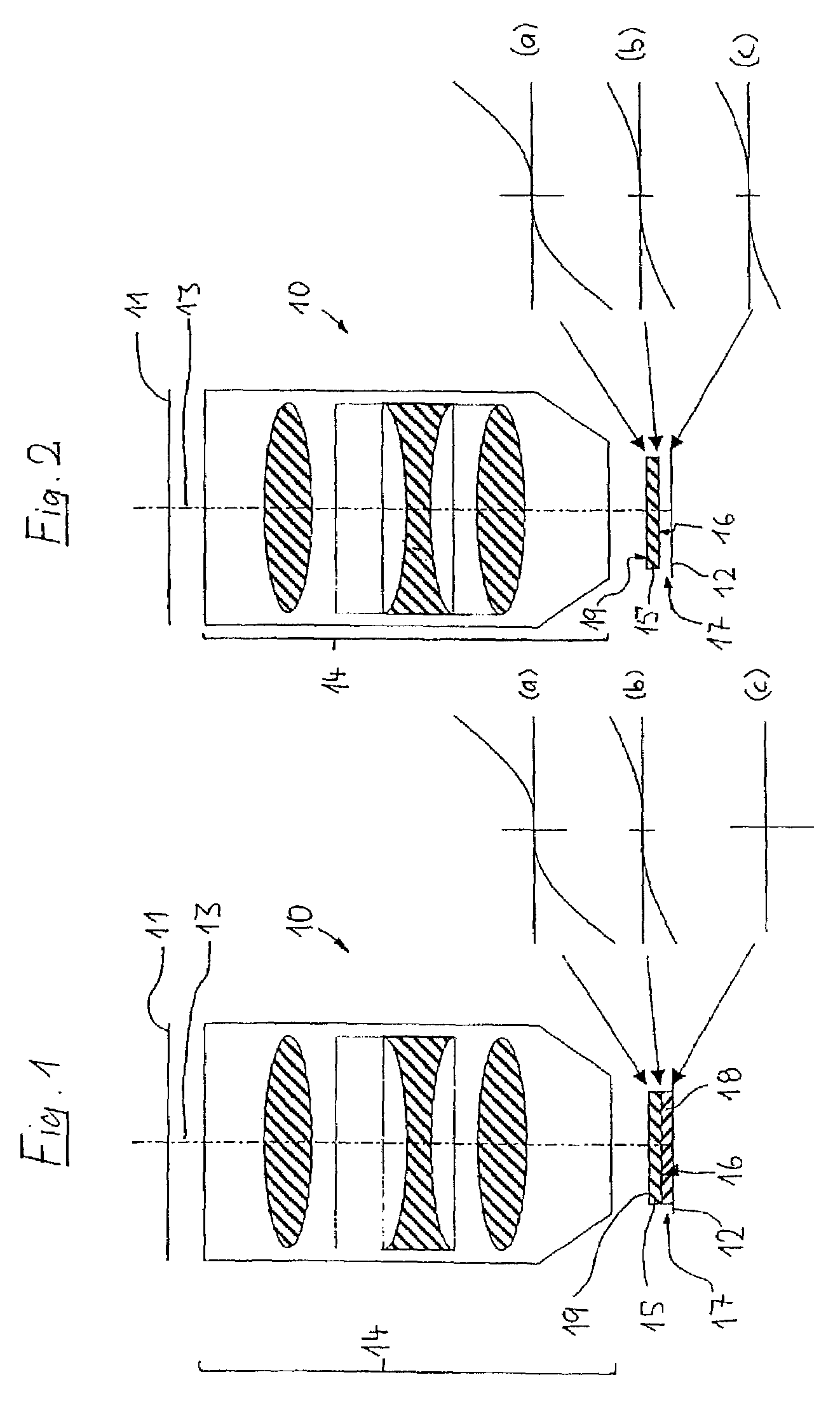
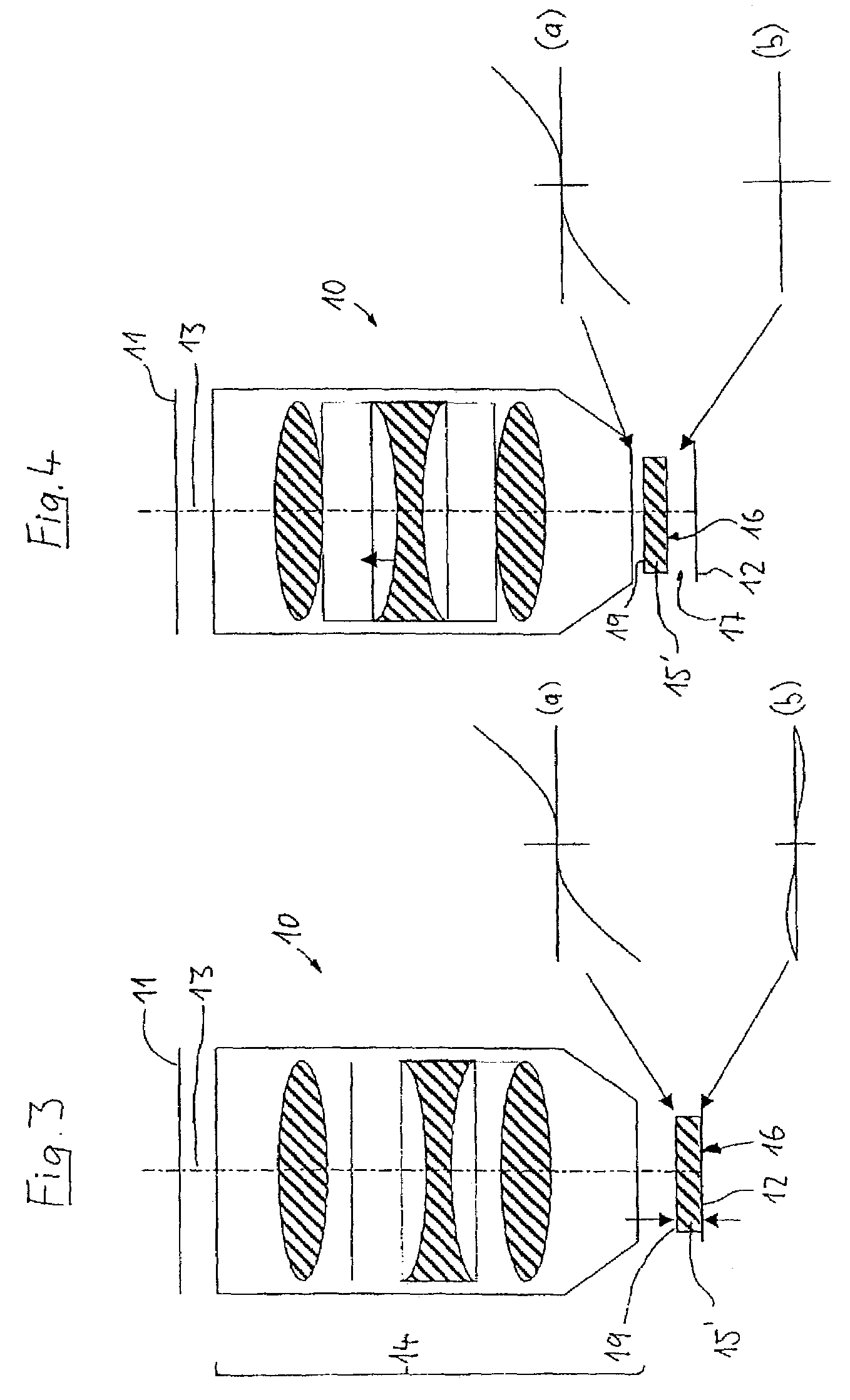
[0062]FIG. 1 shows in schematic form a refractive projection objective 10 for the microlithographic production of semiconductor components and other finely structured components. The reduction objective, operating from the deep UV range (DUV), is used to project patterns of photomasks (reticles) which are arranged in the object plane 11 of the projection objective on a reduced scale onto a semiconductor wafer which is coated with photoresist and is to be arranged in the image plane 12 of the projection objective. The projection objective has a large number of optical elements in the form of lenses of synthetic quartz glass, which are arranged along the optical axis 13 of the system. The optical elements comprise a first group 14 immediately following the object plane, and a last optical element 15, which follows the first group 14 and lies closest to the image plane 12. The last optical element will also be referred to below as the terminating element 15; it can consist of one or mo...


PUM


Abstract

A method of adjusting a projection objective permits the projection objective to be adjusted between an immersion configuration and a dry configuration. The projection objective includes optical elements arranged along an optical axis thereof, which include a first group of elements following the object plane and a last optical element following the first group, which is arranged near the image plane. The last optical element defines an exit surface of the projection objective, which is arranged at a working distance from the image plane. The last optical element is substantially without refracting power and has no or only slight curvature. The method includes varying the thickness of the last optical element, changing the refractive index of the space between the exit surface and the image plane by introducing or removing an immersion medium, and axially displacing the last optical element to set a working distance.

Description

[0001]The following disclosure is based on German Patent Application No. 102 58 718.3 filed on Dec. 9, 2002, which is incorporated into this application by reference.BACKGROUND OF THE INVENTION[0002]1. Field of the Invention[0003]The invention relates to a projection objective for projecting a pattern arranged in an object plane of the projection objective into an image plane of the projection objective, and to a method for adjusting such a projection objective. The preferred field of application is projection objectives for use in microlithography projection exposure systems.[0004]2. Description of the Related Art[0005]Photolithographic projection objectives have been used for many decades for producing semiconductor components and other finely structured components. They are used to project patterns of photomasks or graduated plates (graticules), which are also referred to below as masks or reticles, onto an object coated with a light-sensitive layer, for example onto a semiconduc...

Claims


Application Information

Patent Timeline
IPC IPC(8): G02B3/00G02B15/02G02B27/02G02B13/24G02B13/00G03F7/20H01L21/027
CPCG03F7/70258G03F7/70341G03F7/70308G02B13/00
Inventor EPPLE, ALEXANDERGRAEUPNER, PAULKAISER, WINFRIEDGARREIS, REINERULRICH, WILHELM
Owner CARL ZEISS SMT GMBH
Why Eureka
Try Eureka