Developing apparatus

a technology of developing apparatus and fixing apparatus, which is applied in the field of developing apparatus, can solve the problems of insufficient heating of fixing apparatus of such film type, uneven luster (gloss unevenness) in fixed image, etc., and achieve the effect of suppressing the bonding of fused toner

Active Publication Date: 2007-04-24
CANON KK
View PDF15 Cites 13 Cited by
  • Summary
  • Abstract
  • Description
  • Claims
  • Application Information

AI Technical Summary

Benefits of technology

[0019]Another object of the present invention is to provide a developing apparatus capable of employing a toner that can suppress a fixing failure.
[0020]Still another object of the present invention is to provide a developing apparatus capable of employing a toner that does not cause an image defect such as a gloss unevenness or an offsetting at the fixing operation.
[0021]Still another object of the present invention is to provide a developing apparatus capable of achieving a high speed.

Problems solved by technology

In a full-color developing apparatus, it is not desirable, from the standpoint of color reproducibility, to include a magnetic powder which is generally colored in a full-color developer as a one-component developer.
However, the fixing apparatus of such film heating type is insufficient in a heat amount as a fixing apparatus of a full-color image forming apparatus or a high-speed image forming apparatus requiring a large heat amount for image fixing, and causes drawbacks such as a defective fixation, an unevenness in luster (gloss unevenness) in the fixed image and a toner offsetting, for which further improvements are desired.

Method used


Image

  • Developing apparatus
  • Developing apparatus
  • Developing apparatus

Examples


example 1

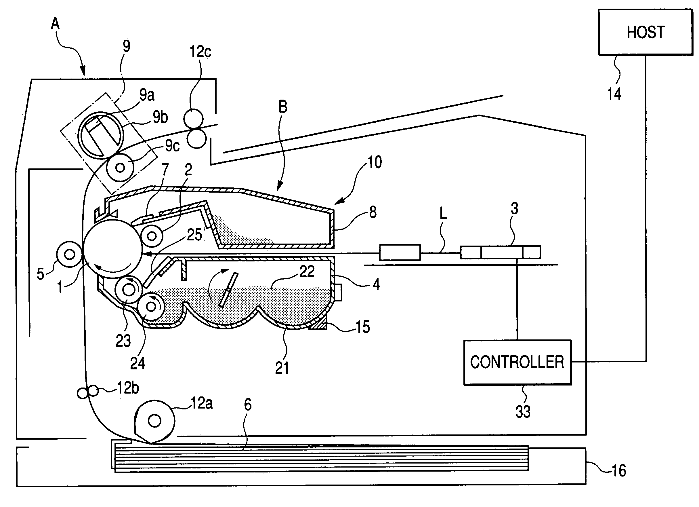
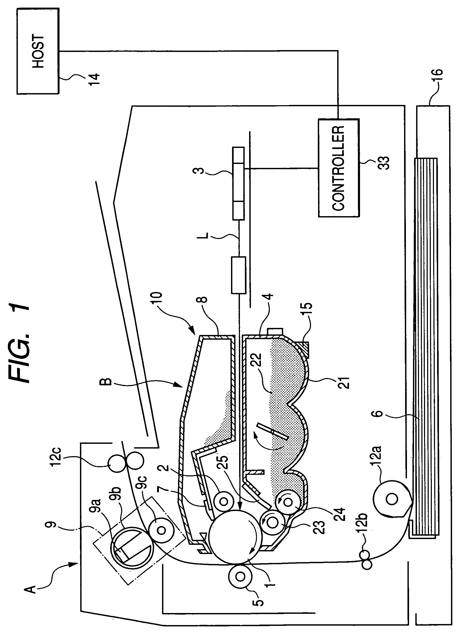
[0032]FIG. 1 is a schematic cross-sectional view of an example of an image forming apparatus capable of utilizing a developing apparatus of the present invention. The image forming apparatus of the present example is a laser beam printer for forming an image by an electrophotographic process according to image information, on a recording medium 6 such as a recording paper or an OHP sheet. The image forming apparatus is provided with a main body A of the image forming apparatus, and a process cartridge B, wherein the process cartridge B is detachably mounted in the main body A of the image forming apparatus as will be described later in more details.

[0033]The image forming apparatus is used by connecting to a host apparatus 14 such as a personal computer. The process cartridge B is provided with a photosensitive member (photosensitive drum) 1 of a drum shape as an image bearing member, and image forming means is provided along an external periphery of the photosensitive drum 1. In th...

example 2

[0095]This example explains an influence of a hardness of the developing roller 23 in an image formation utilizing the toner 22b shown in Table 1. In the present example, there was employed a developing roller 23 having a surface roughness Ra=1.2 μm, Rz=10 μm and Sm=100 μm meeting the relationships (12) shown above.

[0096]Table 3 shows a relationship, after 20,000 image formations in an image forming apparatus under an environment of a normal temperature and a normal humidity (25° C. / 60%), a hardness of the developing roller 23, an image fog, and surface layer peeling of the roller 23 and a developing line appearing on the image. The developing line is caused by a fused toner bonding onto the developing blade 23 by a friction between the developing roller 23 and the developing blade 25, and is a streak extended in the longitudinal direction (direction of rotation axis) of the developing roller.

[0097]

TABLE 3After 20,000Asker-CMD-1image formationshardnesshardnessFogdeveloping line3520−...

example 3

[0102]In the present example, in an image forming apparatus of a configuration similar to that in Example 1, an even better setting of the developing blade in the developing apparatus 4 is considered.

[0103]The developing apparatus shown in FIG. 1 executes, as explained in the example 1, a one-component developing method in which a charge is given to the toner 22 by a friction between the developing blade 25 and the developing roller 23. Therefore a positional arrangement of the developing blade 25 and the developing roller 23 is important, and an abutment pressure P of the blade 25 on the developing roller 23 is considered.

[0104]A non-magnetic toner subjected to a spherical treatment is not easily regulated in the coating amount by the developing blade 25 because of the spherical shape. In order to realize a satisfactory image quality, it is necessary to increase a regulating force by the developing blade 25.

[0105]An image forming operation was conducted by varying an abutment press...


PUM

PropertyMeasurementUnit
temperatureaaaaaaaaaa
viscosityaaaaaaaaaa

Abstract

A developing apparatus including: a developer carrying member for carrying a developer, the developer carrying member being provided with an elastic layer and adapted to develop, with a developer, an electrostatic image formed on an image bearing member; wherein the developer includes a toner, the toner has a shape factor SF-1 of 100 or more but less than 130, the toner has a storage modulus G′ (140° C.) at 140° C. of 2.0×10³ dN / m2 or more but less than 2.0×10⁴ dN / m2, the toner has a temperature, when the toner has a viscosity of 1.0×10³ Pa·s in a flow tester temperature elevation method, of 115° C. or more but less than 130° C., and, in a surface roughness of the developer carrying member, a center-line mean roughness Ra, a ten-point mean roughness Rz and a mean spacing Sm of irregularities satisfy following relationships (1):0.06≤Rz / Sm≤0.40.8≤Ra≤2.0⁢⁢(μ⁢⁢m)}.(1)

Description

BACKGROUND OF THE INVENTION[0001]1. Field of the Invention[0002]The present invention relates to a developing apparatus for developing an electrostatic latent image formed on an image bearing member with a developer, adapted for use in an image forming apparatus such as a copying apparatus or a printer.[0003]2. Related Background Art[0004]An image forming apparatus utilizing an electrophotographic process is utilized, in addition to a copying apparatus, as an electrophotographic image forming apparatus such as a printer or a facsimile apparatus. Particularly in a printer or a facsimile, for the purpose of reducing the dimension of a copying apparatus portion and of facilitating maintenance, a unit formation is progressing in a developing unit constructed around a developing apparatus and a drum unit constructed around an electrostatic latent image bearing member (image bearing member), and a process cartridge integrating these units is employed frequently.[0005]Also such process car...

Claims


Application Information

Patent Timeline
Patent Type & Authority Patents(United States)
IPC IPC(8): G03G15/08G03G9/087G03G9/08
CPCG03G9/0819G03G9/0821G03G9/0823G03G9/0827G03G9/08711G03G9/08795G03G9/08797G03G15/08G03G2215/0617
Inventor KOYANAGI, MASATOKOBAYASHI, TETSUYAYAMAMOTO, SHINYAMATSUDA, KOHEIAGATA, SHINICHIKAWATA, KENTAROUMORIKI, YUJI
Owner CANON KK
Why Eureka
Try Eureka