Light source unit and projector

a light source and projector technology, applied in the field of light source units and projectors, can solve the problems of difficult to efficiently collimate light, and difficult to effectively use the luminous flux from the light source part, so as to achieve enhanced light utilization efficiency, high light utilization efficiency, and the effect of increasing the rate of being transmitted through the polarization splitter film

Active Publication Date: 2007-05-01
SEIKO EPSON CORP
View PDF9 Cites 9 Cited by
  • Summary
  • Abstract
  • Description
  • Claims
  • Application Information

AI Technical Summary

Benefits of technology

[0011]Furthermore, in order to guide the light from the surface emitting part in a specific direction, in place of a hemispherical lens, the conical lens or pyramid lens is used. Accordingly, the image of the surface emitting part is never magnified and formed. Thereby, the spatial extent of the image of the surface emitting part can be reduced. Therefore, since etendue is conserved, when the spatial light modulator unit is illuminated, the angle that can be taken by the spatial light modulator unit becomes larger. In addition, when the light emitted from the light source unit is collimated by a collimator lens, because the spatial extent is small, the light can be collimated efficiently.
[0019]Further, a projector according to a second exemplary aspect of the invention, includes: the above described light source unit; a spatial light modulator unit to modulate light from the light source unit in response to an image signal; and a projection lens to project the modulated light. Thereby, a bright projection image can be obtained using light flow the light source unit with high light utilization efficiency.

Problems solved by technology

On this account, it is difficult to effectively use the luminous flux from the light source part.
However, since the planer emitting region of the solid-state surface emitting source has a constant extent and it is not a point light source, it is difficult to efficiently collimate the light.
On this account, it is difficult to effectively use the luminous flux from the light source part.
Furthermore, in the case where the light output from the hemispherical lens is collimated by the collimated lens as described above, because the light source has an extent, it is difficult to effectively collimate the light.
Thereby, it is difficult to effectively use the luminous flux from the light source part.

Method used


Image

  • Light source unit and projector
  • Light source unit and projector
  • Light source unit and projector

Examples


exemplary embodiment 1

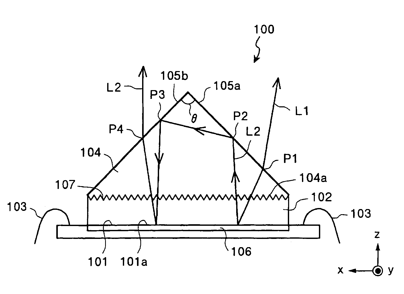
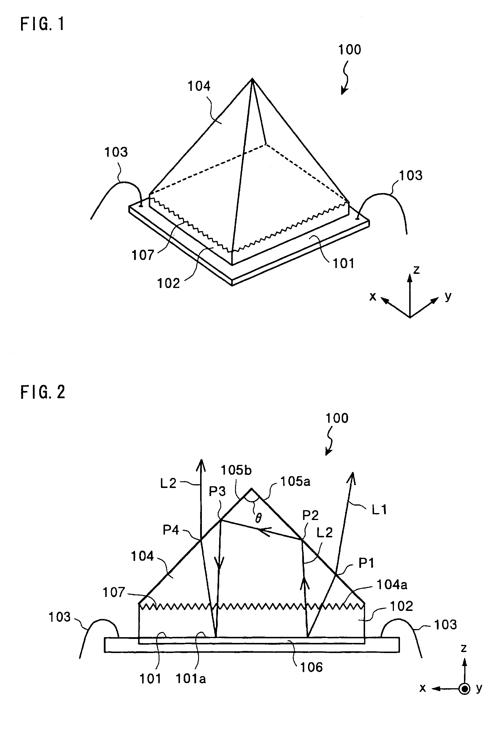
[0033]FIG. 1 is a schematic of a light source unit 100 according to exemplary embodiment 1 of the invention. The light source unit 100 is a surface emitting LED. Further, FIG. 2 shows the sectional constitution of the light source unit 100. In FIG. 2, a surface emitting part 101 is formed by allowing a crystal of Ga, In, N, or the like to grow on a sapphire substrate 102. On ends of the surface emitting part 101, bonding wires 103 are provided. The surface emitting part 101 emits light with substantially equal intensity in all directions from a planer emitting region 101 a. That is, the surface emitting part 101 functions as a so-called Lambertian surface. Additionally, on one surface side of the surface emitting part 101, a reflecting metal electrode 106 as a reflecting part is provided. Further, on the other surface side of the surface emitting part 101, a square pyramid prism 104 including an optical transparent member of high refractive index glass is fixed with an optical adhes...

exemplary embodiment 2

[0042]FIG. 5 is a schematic of a light source unit 500 according to exemplary embodiment 2 of the invention. The square pyramid prism is used in exemplary embodiment 1, but exemplary embodiment 2 is different in the point where a conical prism is used. Other basic constitution is the same as in exemplary embodiment 1, and the same parts as in exemplary embodiment 1 are assigned with the same signs and overlapping description will be omitted. The light source unit 500 is a surface emitting LED. A circular surface emitting part 101 is formed by allowing a crystal of Ga, In, N, or the like to grow on a sapphire substrate 102. On ends of the circular surface emitting part 101, bonding wires 103 are provided. The surface emitting part 101 emits light with substantially equal intensity in all directions from a planer emitting region. That is, the surface emitting part 101 functions as a so-called Lambertian surface. Additionally, on one surface side of the surface emitting part 101, a ref...

exemplary embodiment 3

[0044]FIG. 6-1 is a schematic of a light source unit 600 according to the exemplary embodiment 3 of the invention. The exemplary embodiment is different from exemplary embodiment 1 in the point where polarized light in a specific vibrating direction is output in a specific direction. The same parts as in the above described exemplary embodiment 1 are assigned with the same signs and overlapping description will be omitted. The light source unit 600 is a surface emitting LED. Further, FIG. 6-2 is a view of the light source unit 600 seen from the direction of an apex angle θ of a square pyramid prism 604 (z axis direction). The apex angle θ is 90°. In FIG. 2, a surface emitting part 101 is formed by allowing a crystal of Ga, In, N, or the like to grow on a sapphire substrate 102. On ends of the surface emitting part 101, bonding wires 103 are provided. The surface emitting part 101 emits light with substantially equal intensity in all directions from a planer emitting region. That is,...


PUM

PropertyMeasurementUnit
apex angleaaaaaaaaaa
angleaaaaaaaaaa
refractive indexaaaaaaaaaa

Abstract

The enclosed embodiments provide a light source unit and a projector with high light utilization efficiency. The unit has a light emitting part for emitting light from a planer emitting region, a reflecting metal electrode provided on one side of the light emitting part, a square pyramid prism on the other side of the light emitting part, and a bottom surface of the prism that has substantially the same size and shape as the planer emitting region. The inclined surfaces of the square pyramid prism output light that has entered the square pyramid prism from the bottom surface in a specific direction. The reflecting metal electrode reflects the light that has been reflected by the inclined surfaces and transmitted through the bottom surface of the square pyramid prism.

Description

BACKGROUND OF THE INVENTION[0001]1. Field of Invention[0002]Exemplary aspects of the present invention relate to a light source unit and a projector with the light source unit.[0003]2. Description of Related Art[0004]A related art solid-state light emitting source, such as an LED, specifically, a solid-state surface emitting source to emit light from a planer emitting region is used as a light source part. Further, Tsunemasa TAGUCHI, “Technology for Realizing High-brightness, High-efficiency, and Long Lifetime of White LED System”, Technical Information Institute Co., Ltd., Mar. 27, 2003, pp. 47–50 discloses enhancing luminous efficiency of the solid-state surface emitting source.SUMMARY OF THE INVENTION[0005]A solid-state surface emitting source can be used as a light source part of a projector. In this case, it is necessary to consider not only the luminous efficiency of the light source, but also utilization efficiency of light in an optical system including a spatial light modul...

Claims


Application Information

Patent Timeline
Patent Type & Authority Patents(United States)
IPC IPC(8): G03B21/28G02B5/02G02B5/04G02B5/08G02B27/14G02B27/28G02F1/13G02F1/1335G02F1/13357G03B21/00G03B21/14G03B21/20H04N9/31
CPCG02B5/04G02B27/1046H04N9/3197G02B27/149H04N9/315G02B27/144G03B21/14G03B21/20
Inventor YONEKUBO, MASATOSHI
Owner SEIKO EPSON CORP
Why Eureka
Try Eureka