
Inductive charging system

Inactive Publication Date: 2007-05-01
PLANTRONICS
View PDF16 Cites 249 Cited by
  • Summary
  • Abstract
  • Description
  • Claims
  • Application Information

AI Technical Summary

Problems solved by technology

However, use of surface contacts and a charging base station with a headset presents problems due to the smaller physical size and design of headsets.
Exposed metal contacts on headsets also risk contamination by oils and moisture from the skin of the wearer.
This may cause corrosion and hence poor contact with the base station.
Contamination also may cause an electrical leakage path that may cause power loss from the battery and electrolytic activity.
Exposed metal contacts may also result in an allergic reaction to the user if in prolonged contact with the user's skin.
During the rechargeable device docking process, the formed ends of the base station charging contacts often come into contact with the plastic housing of the rechargeable device and can scratch the housing and pick up contamination which can cause intermittent electrical contact.
However, this solution may compromise the rechargeable device industrial design, aesthetics, and possibly weaken the rechargeable device structural integrity.
Furthermore, the headset or other rechargeable device may not be firmly detented with the charging base, which may also cause intermittent electrical contact.
However, this solution compromises the industrial design of the rechargeable device, and in addition the detent force is less than robust.
As electronic items become smaller and the regulatory requirements become more stringent, the charging port becomes more noticeable as a relatively large unattractive feature of the housing, as an ESD weakness, as a relatively unreliable element in the system.
This means that generally these charging methods are custom designed for the appliance due to non standardization of the interface and can require dexterity to use.
The costs of the design of the charging system and the additional mechanical design have to be born by the individual product.
This has restricted the adoption of contactless charging systems.
Furthermore, prior art solutions often allow charging of only one item at a time.
As the number of devices used by an individual increases, the multiplicity of chargers becomes problematic.

Method used


Image

  • Inductive charging system
  • Inductive charging system
  • Inductive charging system

Examples


Embodiment Construction

[0032]The present invention provides a solution to the needs described above through an inventive inductive battery charger.

[0033]Other embodiments of the present invention will become apparent to those skilled in the art from the following detailed description, wherein is shown and described only the embodiments of the invention by way of illustration of the best modes contemplated for carrying out the invention. As will be realized, the invention is capable of modification in various obvious aspects, all without departing from the spirit and scope of the present invention. Accordingly, the drawings and detailed description are to be regarded as illustrative in nature and not restrictive.

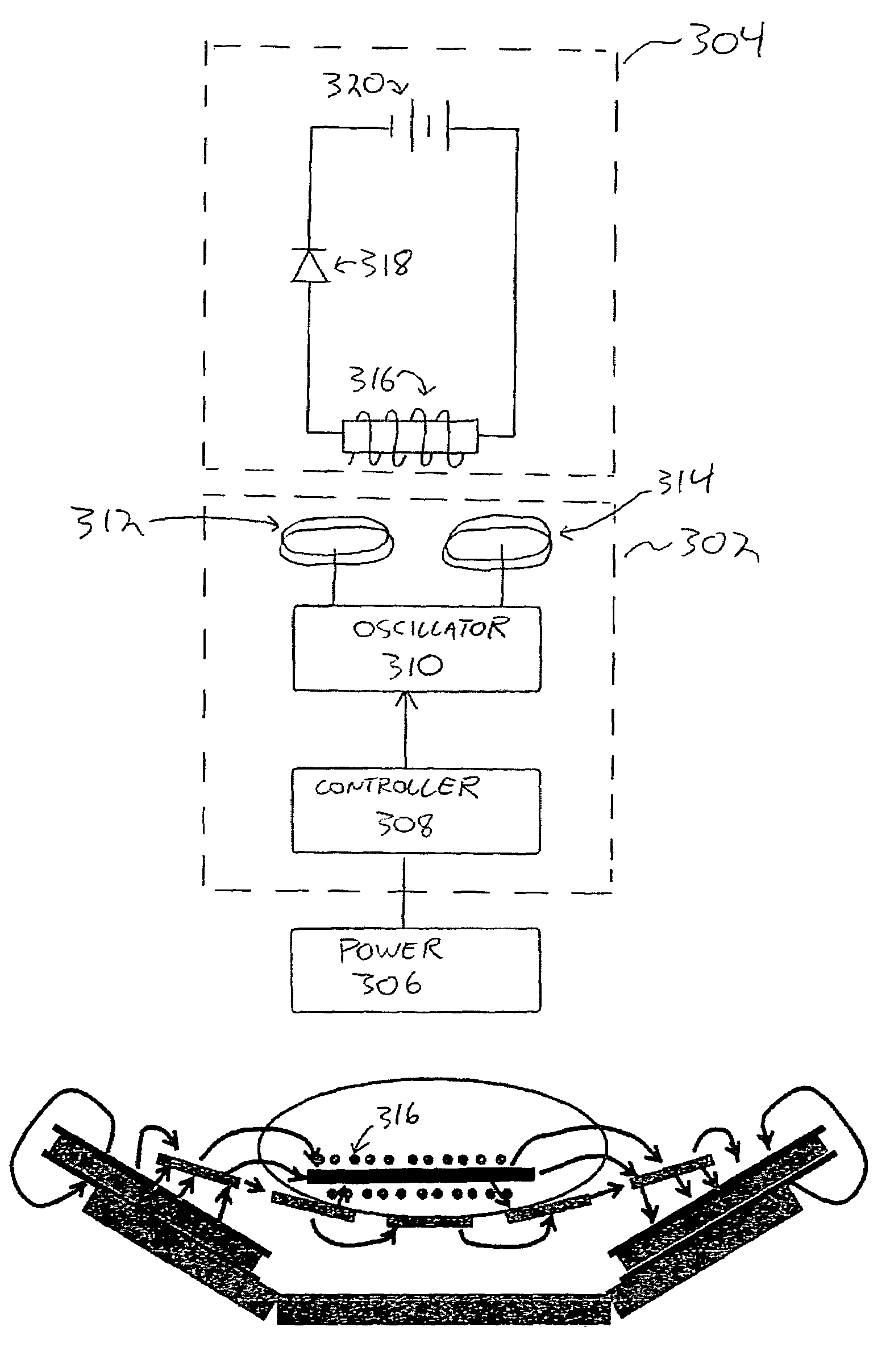
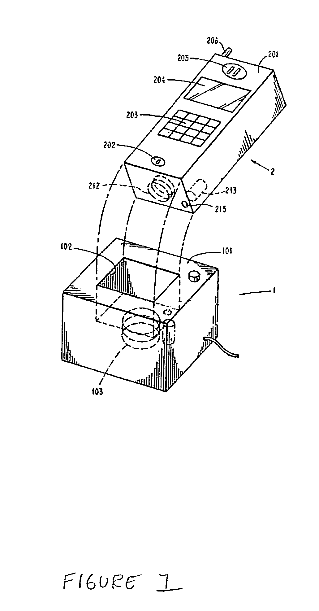
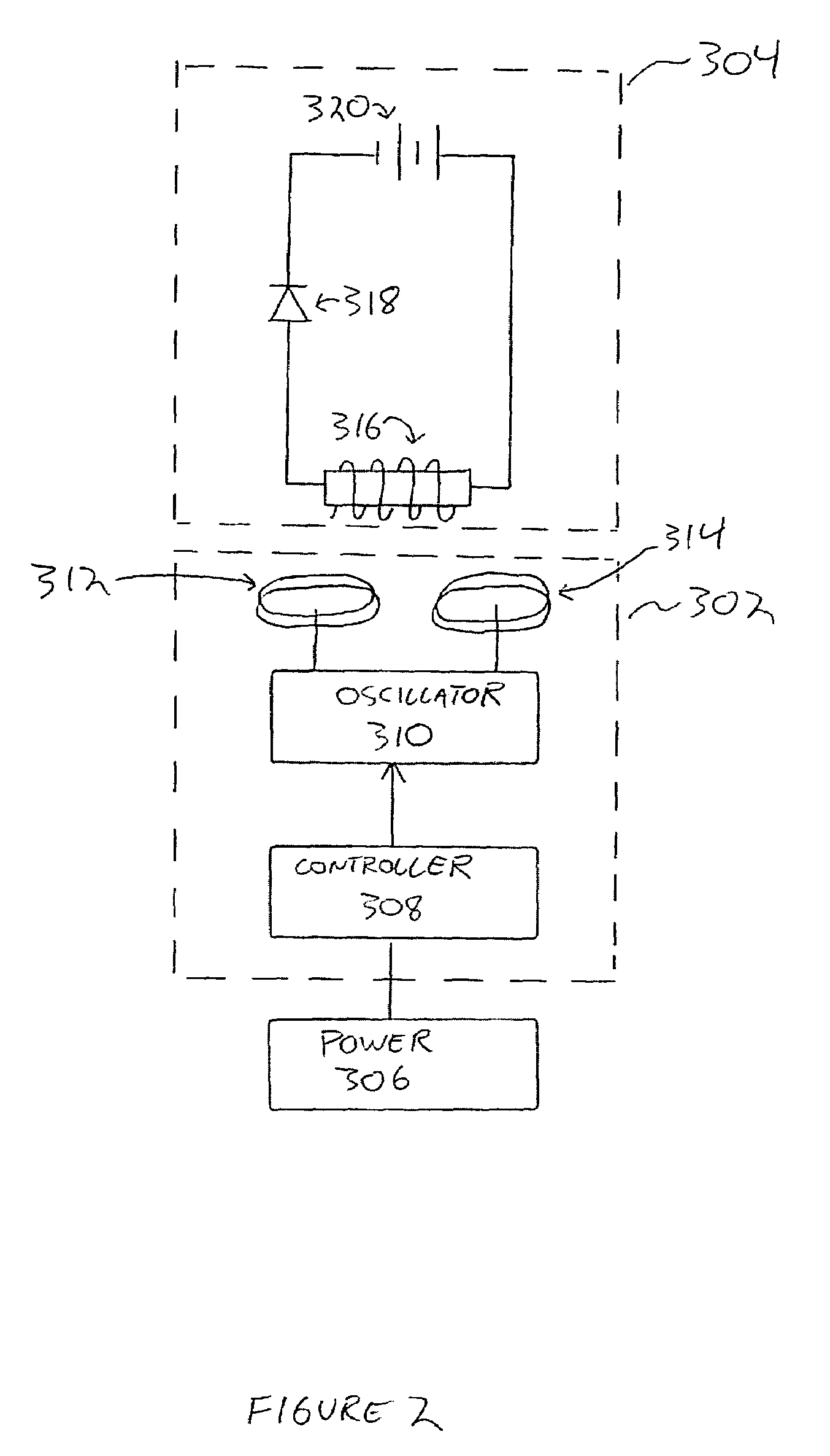
[0034]The present invention provides a contactless charging system utilizing induction which does not require a housing with a compartment or recess that must be mechanically matched to the item being charged. This creates the opportunity to charge a variety of battery powered electronic items from...


PUM


Abstract

An apparatus for inductive charging a battery. The apparatus includes a housing with a lower surface and a charging surface. A rechargeable device with a rechargeable battery may be placed on the charging surface. The apparatus further includes a controller for driving an oscillator, wherein the controller receives power from a power source. A first charger coil and second charger coil are disposed within the housing and are coupled to the oscillator. The first charger coil and second charger coil create a substantially horizontal magnetic field in the volume of space above the charging surface.

Description

TECHNICAL FIELD[0001]The present invention relates to the general field of charging interfaces. More specifically the invention relates to inductive battery chargers.BACKGROUND[0002]Wireless headsets and other portable communications devices are often battery powered such that a user can use the wireless headset or other such device without being directly connected to larger power source such as an a / c outlet or automobile battery. This allows wireless headset users flexibility and convenience to move about without being tied to a power cord. Wireless headset batteries are generally rechargeable so that the batteries can be recharged and need not be discarded after use.[0003]Recharging of device batteries has generally achieved by a wired connection. In the prior art, devices employing rechargeable batteries typically have charging contacts so that charging current power can be supplied to recharge the batteries without removing the batteries from the device. In one typical setup, t...

Claims


Application Information

Patent Timeline
IPC IPC(8): H02J7/00
CPCH02J7/025H02J7/0044H02J50/402H02J7/0045H02J50/005H02J50/80H02J50/60H02J50/12H02J50/70H02J5/00
Inventor FLOWERDEW, PETER M.HUDDART, DAVID
Owner PLANTRONICS
Features
  • Generate Ideas
  • Intellectual Property
  • Life Sciences
  • Materials
  • Tech Scout
  • Unparalleled Data Quality
  • Higher Quality Content
  • 60% Fewer Hallucinations
Learn More