Engine airflow management system

a management system and airflow technology, applied in the direction of valve arrangements, oscillatory slide valves, machines/engines, etc., can solve the problems of insufficient airflow characteristics of poppet valve assemblers, inability to complete air or air/fuel mixture entry into the cylinder at the beginning of an induction stroke of a four-stroke internal combustion engine, and high cost of manufacturing, assembly and maintenance of such assemblies, etc., to achieve greater flow capability

Inactive Publication Date: 2007-05-08
VERMEER STEVEN
View PDF20 Cites 5 Cited by
  • Summary
  • Abstract
  • Description
  • Claims
  • Application Information

AI Technical Summary

Benefits of technology

[0016]One of the benefits of the rotary valve mechanism of the present invention is that the intake port cutout may be constructed and arranged to remain open during substantially an entire induction stroke of the four-stroke engine. What is more, the intake port cutout will typically fully open the intake port within 45 degrees of rotation of the crankshaft to which the valve cylinder is coupled. The solid cross-sectional area of the ports offers a much greater flow capability than the annular flow area presented by a typical prior art poppet valve. And, as the intake port typically remains open for between 180 and 182 degrees of rotation of the crankshaft to which the valve cylinder is coupled, larger quantities of fuel / air mixture burned in the cylinders may be brought into the cylinder for combustion.

Problems solved by technology

The costs associated with manufacturing, assembling, and maintaining such an assembly are quite high.
Furthermore, the airflow characteristics associated with poppet valve assembles 20 are relatively inefficient as air, fuel, and combustion gases must enter or exist the cylinder 26 through a relatively small annular opening created between the poppet valve head 36 and valve seat 38 when the poppet valves 34 are opened.
Therefore, entry of air or an air / fuel mixture into the cylinder at the beginning of an induction stroke of a four-stroke internal combustion engine may not be complete, and similarly, the flushing of combustion gases that takes place during the exhaust stroke may not be complete either.
This situation typically results in less than ideal combustion within the cylinder 26.
Because a poppet-type valve assembly is such a complex mechanism, it is difficult to arrange an engine's components into a given engine compartment space.
The difficulty in positioning the valve assembly 20 is further complicated by the need to provide cooling to the assembly.
Such coolant passages 23 may not be able to sufficiently cool the valve assembly 20 when the engine 2 is under high stress.
Subsequently, valve assemblies 20 may quickly become overheated and may become damaged.
These mechanisms are typically even more complex than the poppet valve 20 and correspondingly more expensive.

Method used


Image

  • Engine airflow management system
  • Engine airflow management system
  • Engine airflow management system

Examples


Embodiment Construction

[0038]Although the disclosure hereof is detailed and exact to enable those skilled in the art to practice the invention, the physical embodiments herein disclosed merely exemplify the invention, which may be embodied in other specific structure. While the preferred embodiment has been described, the details may be changed without departing from the invention, which is defined by the claims.

[0039]A valve assembly constructed according to the present invention may be readily adapted for use with four stroke and two stroke engines as well as with engines that operate on more complex principles. Furthermore, the present invention may be utilized with engines that burn gas, diesel, natural gas, kerosene or other combustibles.

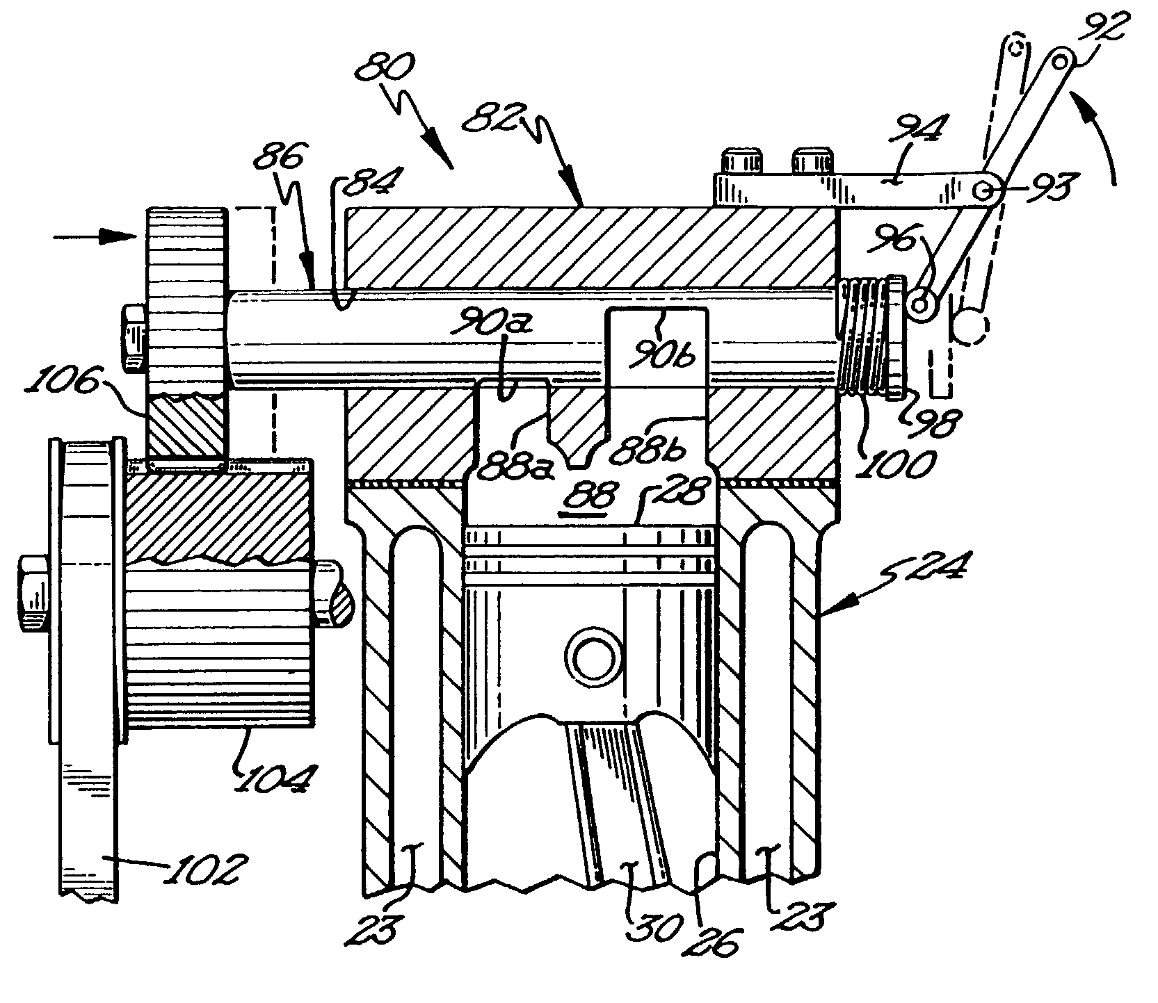
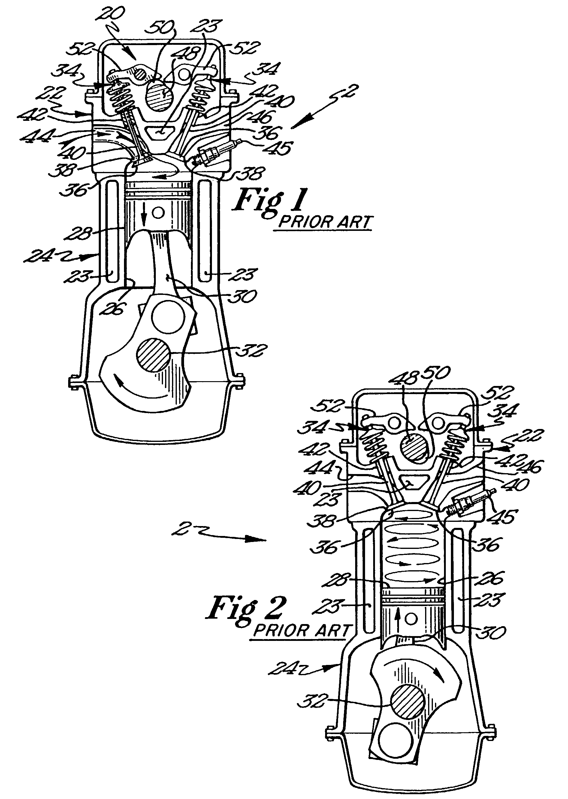
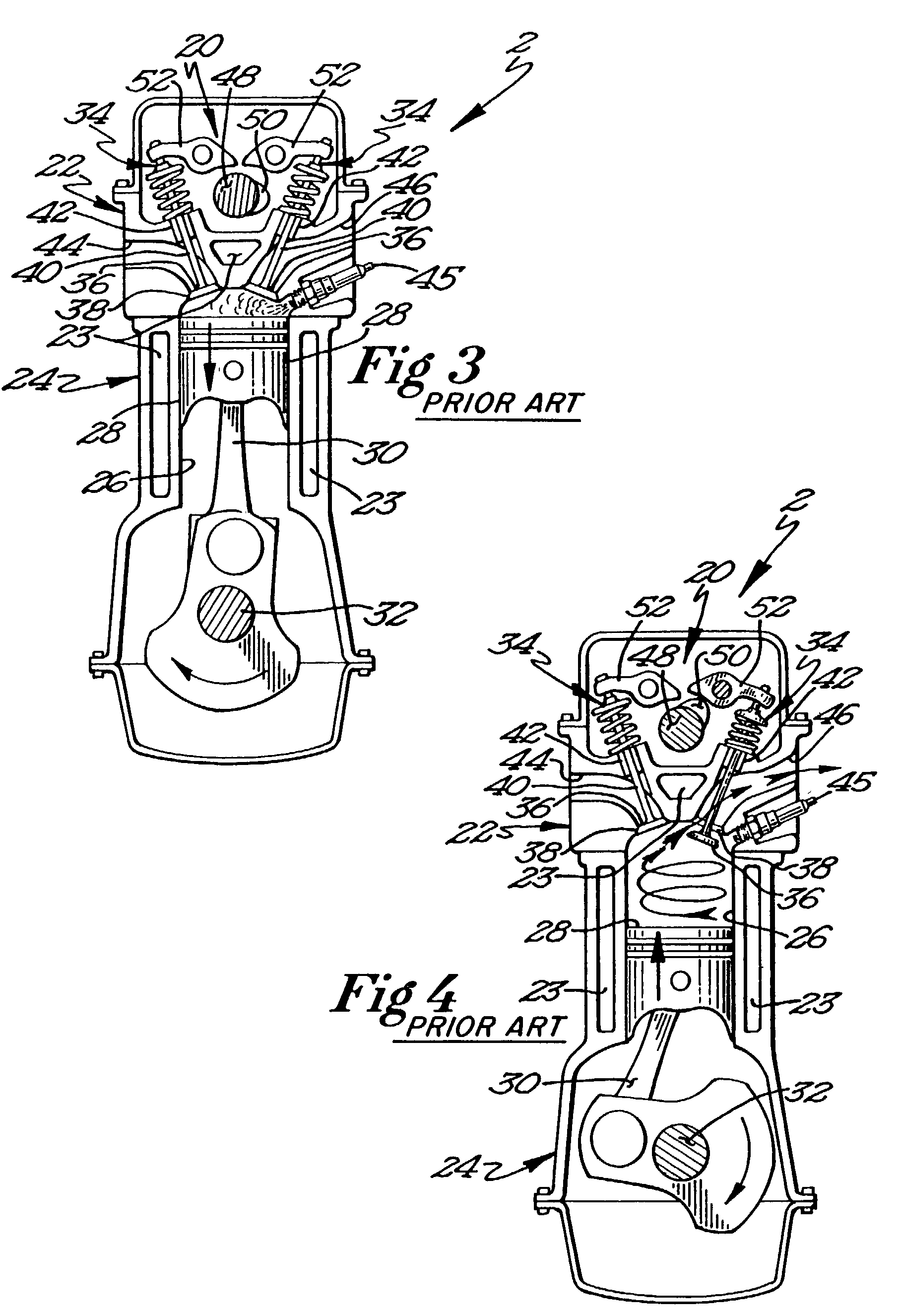
[0040]Throughout this specification, top dead center refers to the uppermost position of the piston 28 within the cylinder 26. The lowermost position of the piston 28 within cylinder 26 is known as bottom dead center. The piston 28 reciprocates within the cylinder 26...


PUM


Abstract

A rotary valve assembly for an internal combustion engine is herein disclosed. The rotary valve assembly comprises a valve body having a number of ports formed therethrough and a bore that intersects these ports such that a valve cylinder inserted into the bore may selectively occlude or open the ports of the valve body. Cutouts formed into the valve cylinder facilitate the opening of the ports as they are rotated into alignment with the ports of the valve body. The rotary valve assembly may be used as a throttle mechanism by sliding the valve cylinder longitudinally within the bore of the valve body so as to control the aspect of the cutouts or bores formed into the valve cylinder that is presented to the ports.

Description

[0001]This application claims benefit of Provisional U.S. Appl. No. 60 / 277,762, filed Mar. 21, 2001.FIELD OF THE INVENTION[0002]The present invention relates to an intake / exhaust valve for an internal combustion engine and more specifically to a rotary intake / exhaust valve that may also incorporate a throttling mechanism.BACKGROUND OF THE INVENTION[0003]Virtually all internal combustion engines on the market today utilize poppet type valves. FIGS. 1–4 illustrate schematically a single cylinder of a prior art internal combustion engine having typical poppet-type intake and exhaust valves installed therein. The poppet valve assembly 20 illustrated in FIGS. 1–4 typically resides in the head 22 of the internal combustion engine 2. Head 22 is bolted to the block 24 of the engine 2 immediately over cylinder 26. Piston 28 is slidably received within cylinder 26 in close fitting conformity therewith. The crank arm 30 is coupled between the piston head 28 and crankshaft 32, thereby translati...

Claims


Application Information

Patent Timeline
Patent Type & Authority Patents(United States)
IPC IPC(8): F01L7/00F01L1/344F01L7/02
CPCF01L1/34403F01L7/021F01L7/022
Inventor VERMEER, STEVEN
Owner VERMEER STEVEN
Why Eureka
Try Eureka