Resonator method and system for distinguishing characteristics of surface features or contaminants

a surface feature and resonance technology, applied in the field of optical systems, can solve the problems of scatterometer not revealing scatterometer not providing sufficient measurement energy to measure a very small isolated artifact,

Inactive Publication Date: 2007-05-08
XYRATEX TECH LTD
View PDF11 Cites 17 Cited by
  • Summary
  • Abstract
  • Description
  • Claims
  • Application Information

AI Technical Summary

Problems solved by technology

At present, only limited possibilities exist for examining a surface to locate defects or other features and determine a type of defects.
However, a scatterometer does not reveal information about the material type of an artifact, only the artifact's scattering profile.
Also, a scatterometer also does not typically provide sufficient measurement energy to measure a very small isolated artifact and is typically used more generally to detect, for example, when a surface is contaminated with dust particles.
Scatterometers are also insensitive to the height of artifacts as well as the direction of the height variations, but are very sensitive to artifact shape, which severely limits the information they can provide about the material nature of an artifact.
In general, other available systems and techniques that can observe a single artifact and reveal information about the artifact's material composition are very expensive, are typically too slow for a production environment and are generally laboratory instruments with capabilities extending far beyond those needed for the production inspection environment or for data detection applications.
While the powerful range of measurement capability provided by the laboratory instruments mentioned above is not typically needed in a production inspection environment (typically the types of surface artifacts being detected is limited to a fairly small set of possibilities), there is no present alternative for the production inspection environment that provides the ability to distinguish amongst types of artifacts, both with respect to the cost of the instrument and the speed with which a surface can be inspected.
The reference resonator system, as well the other systems described in the U.S. patent applications incorporated in the parent application, are suitable for production environments but do not in themselves provide the ability to distinguish the material characteristics of an artifact detected on a surface of interest or examine the relation between the size of an artifact and the artifact's material composition.

Method used


Image

  • Resonator method and system for distinguishing characteristics of surface features or contaminants
  • Resonator method and system for distinguishing characteristics of surface features or contaminants
  • Resonator method and system for distinguishing characteristics of surface features or contaminants

Examples


Embodiment Construction

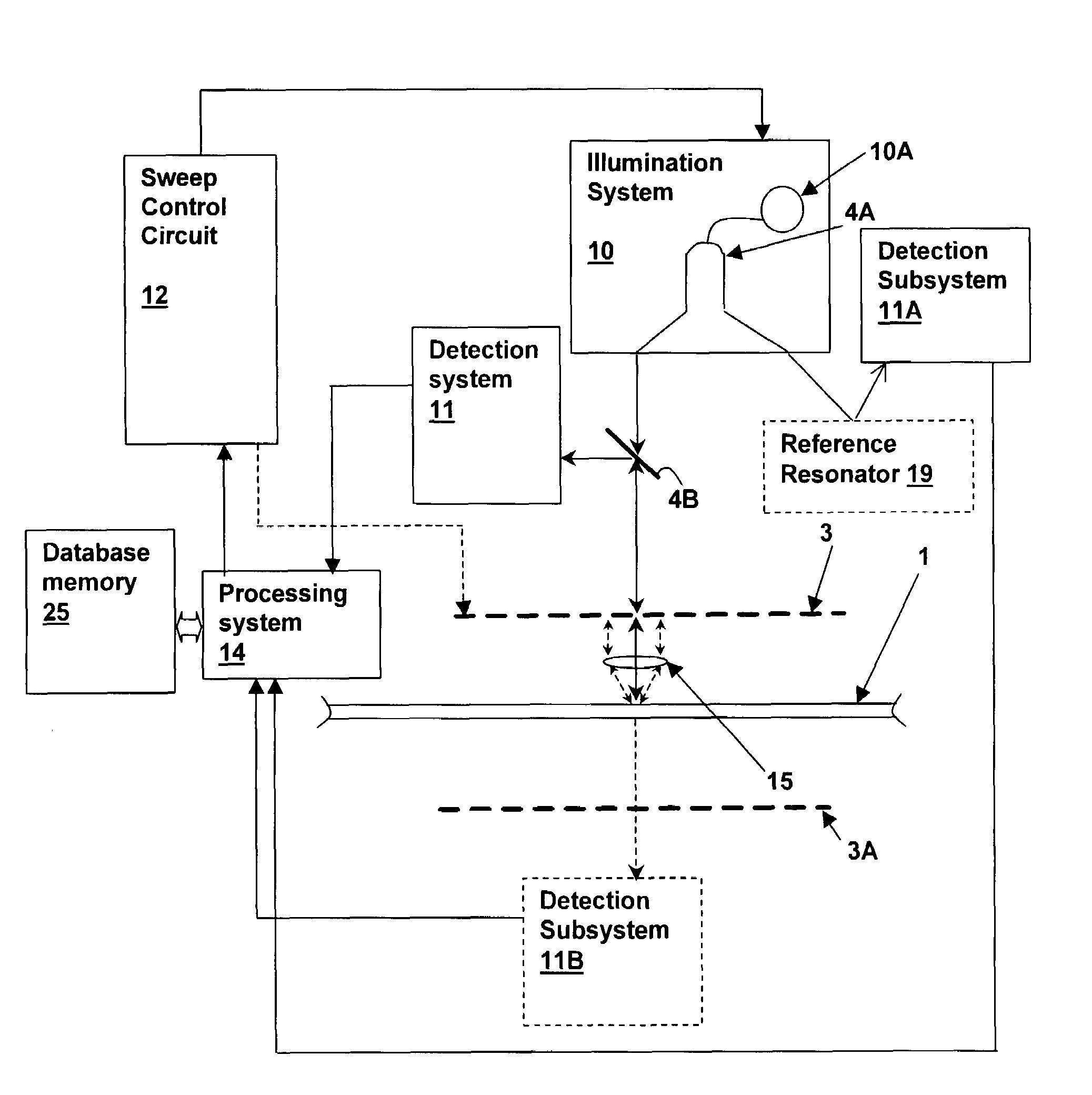
[0025]The above-incorporated parent application describes a dual resonator swept-wavelength technique and system that can be used to improve the performance of various resonator-enhanced optical systems. In general, the parent application, its parent applications and the above-incorporated co-pending U.S. patent applications disclose a variety of techniques and systems using a resonator that enhance the measurement of optical properties of a surface.

[0026]However, up to this point, it has not been possible to reliably distinguish between artifact types or between artifacts and surface features for small artifacts disposed on or just below a surface under measurement (surface of interest). While any artifact or feature present on or in a surface of interest will generally change the optical properties of the surface in the region of the artifact, the systems disclosed in the above-incorporated patent applications measure only an intensity profile as the illumination beam is scanned o...


PUM

PropertyMeasurementUnit
reflectivityaaaaaaaaaa
wavelengthaaaaaaaaaa

Abstract

A resonator method and system for distinguishing characteristics of surface features or contaminants provides improved inspection or surface feature detection capability in scanning optical systems. A resonator including a surface of interest in the resonant path is coupled to a detector that detects light leaving the resonator. Changes in the resonance peak positions and peak intensities are evaluated against known changes for standard scatters in order to determine the material characteristics of an artifact at the surface of interest that causes a resonance change. The lateral size of the artifact is determined by de-convolving a known illumination spot size with the changing resonance characteristics, and the standard scatterer data is selected in conformity with the determined artifact size. The differential analysis using resonance peak shifts corresponding to phase and amplitude information provides an identification algorithm that identifies at least one artifact / material type is identified from matching known behaviors of artifacts / materials.

Description

RELATED APPLICATIONS[0001]This application is related to U.S. Provisional Patent Application “RESONANT DETECTION OF SCATTERING PARTICLES”, Ser. No. 60 / 583,343, filed by the same inventors on Jun. 28, 2004, from which benefit under 35 U.S.C. §119(e) is claimed. This application is also a continuation-in part of U.S. patent application “METHOD AND SYSTEM FOR PERFORMING SWEPT-WAVELENGTH MEASUREMENTS WITHIN AN OPTICAL SYSTEM INCORPORATING A REFERENCE RESONATOR”, Ser. No. 10 / 750,747, filed on Jan. 2, 2004, now U.S. Pat. No. 6,879,421, the specification of which is incorporated herein by reference.[0002]The present application is also related to co-pending U.S. patent applications Ser. No. 11 / 143,018 entitled “FABRY-PEROT RESONATOR APPARATUS AND METHOD FOR OBSERVING LOW REFLECTIVITY SURFACES”, filed on Jun. 1, 2005; Ser. No. 11 / 149,094 entitled “FABRY-PEROT RESONATOR APPARATUS AND METHOD INCLUDING AN IN-RESONATOR POLARIZING ELEMENT”, filed on Jun. 8, 2005; and Ser. No. 11 / 156,309 “RESONAN...

Claims


Application Information

Patent Timeline
Patent Type & Authority Patents(United States)
IPC IPC(8): H01J3/14H01J40/14H01J5/16G01N21/21G01N21/86G01N21/94G01N21/95G01V8/00
CPCG01N21/211G01N21/94G01N21/9501G01N21/21
Inventor BRUNFELD, ANDREITOKER, GREGORYCLARK, BRYAN
Owner XYRATEX TECH LTD
Why Eureka
Try Eureka