Radar detector

a detector and radar technology, applied in the field of detectors, can solve the problems of swept frequency plans and rates, insufficient delay to place drivers, and create problems, and achieve the effect of improving sensitivity towards a conventional cw sour

Inactive Publication Date: 2007-05-08
WHISTLER GRP INC THE CORP
View PDF9 Cites 21 Cited by
  • Summary
  • Abstract
  • Description
  • Claims
  • Application Information

AI Technical Summary

Benefits of technology

[0016]Upon receiving partial information from the initial sweep, the detector may repeat this sweep at a slower rate in order to improve sensitivity towards a conventional CW source.

Problems solved by technology

The abundance of swept frequency plans and rates creates a problem.
If the radar detector took an additional 300 milliseconds to determine if it will alert the driver, the delay is not sufficient to place the driver in a position of being seen before he is notified of the radar event further down the road.

Method used


Image

  • Radar detector
  • Radar detector
  • Radar detector

Examples


Embodiment Construction

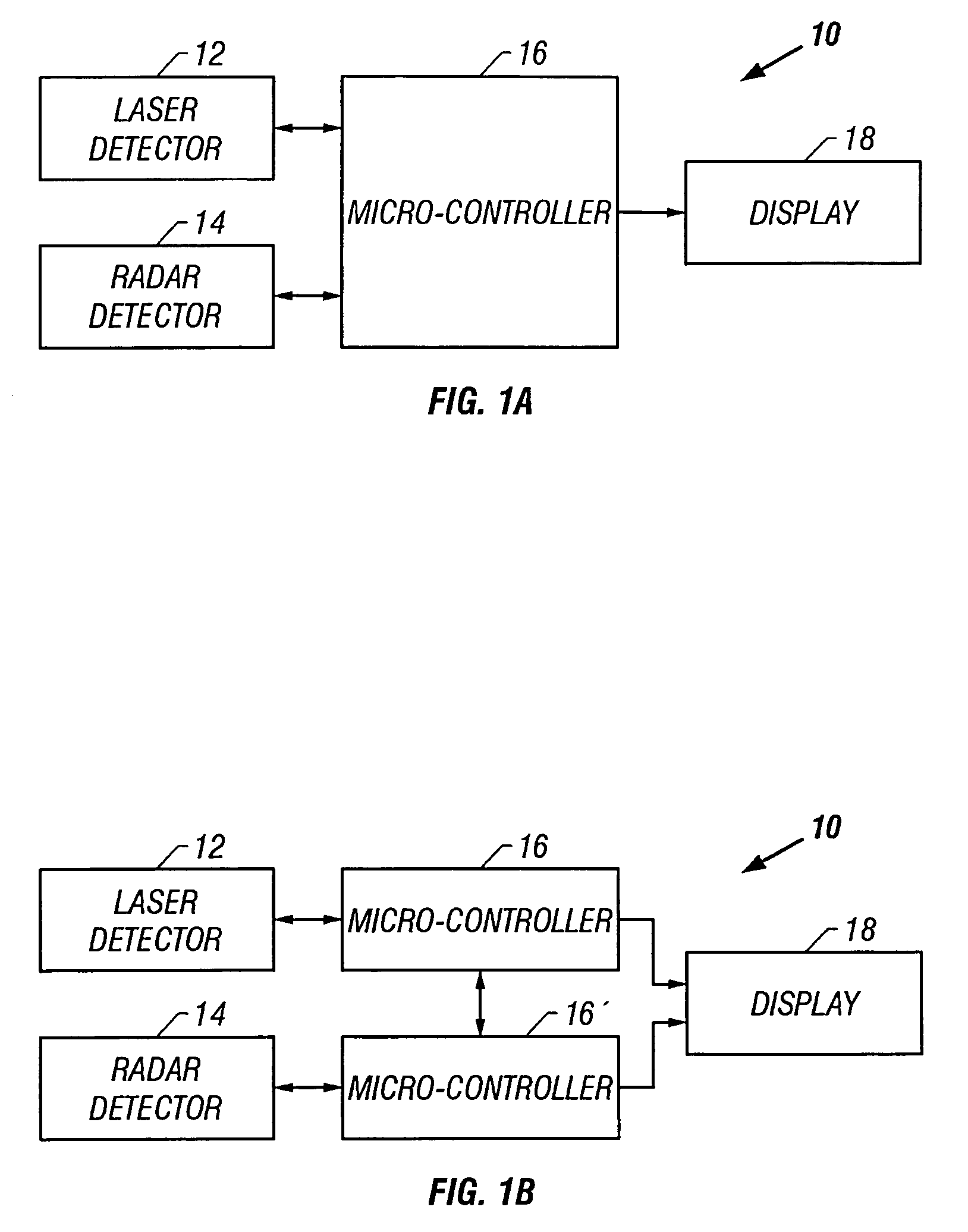
[0030]A block diagram of the electronic assembly of the preferred detector device is presented in FIGS. 1a and 1b. While there are many known electronic assemblies that would be adequate for this application, a device as described in U.S. Pat. No. 5,990,821, the disclosure of which is expressly incorporated herein by reference, will suffice. The detector device is a combination laser / radar detector 10 comprising a laser detector circuit 12 and a radar detector circuit 14. Laser detector circuit 12 and radar detector circuit 14 are each coupled to a microcontroller 16. Microcontroller 16 receives signals fed thereto from each of the laser and radar detector circuits 12, 14 and in response thereto microcontroller 16 provides control signals to the laser and radar detector circuits 12, 14 and to a display 18.

[0031]Displaying means may include, for example, a display screen comprised of light emitting diodes (LEDs). Alternatively or in addition thereto, displaying means may include a li...


PUM


Abstract

A method for detecting radar is provided by the present invention. The invention begins by sweeping a first local oscillator (LO). Once a band has been identified as containing a radar signal, the detector interrupts its normal operation and rechecks the frequency in question for confirmation of CW radar, rather than waiting for the initial sweep to finish. Upon receiving partial information from the initial fast sweep, the detector may repeat this sweep at a slower rate in order to improve sensitivity towards a CW source. If information was from a CW source one can be assured to see the information again when sweeping the same frequency. By contrast, if initial information is from a swept radar detector the information will not be present in the rescan, as the offending radar detector would have moved to a different frequency during the same period of time.

Description

BACKGROUND OF THE INVENTION[0001]1. Technical Field[0002]The present invention relates to a detector device, and more particularly, to a method for decreasing time to respond to police radar while maintaining selectivity towards signals produced by other police radar detectors.[0003]2. Description of the Related Art[0004]As is generally known in the art, speed detection systems may be used to determine the speed of moving objects, such as automobiles and other motorized vehicles. Speed detection systems currently known in the art typically utilize either radar or laser devices in their operation. A speed detection system that utilizes radar may generally be referred to as a so-called radar gun. Radar guns typically include a microwave signal source that emits a signal having a frequency in the radio-frequency electromagnetic spectrum. The radio-frequency spectrum utilized in speed-detection radar devices is divided into a series of bands, with each band covering a range of frequenci...

Claims


Application Information

Patent Timeline
Patent Type & Authority Patents(United States)
IPC IPC(8): H04K3/00G01S13/00G01S7/00
CPCG01S7/022G01S7/4806
Inventor BATTEN, MICHAELAUTIO, CRAIG R.
Owner WHISTLER GRP INC THE CORP
Why Eureka
Try Eureka