Rack-mountable systems

a rack and rack technology, applied in the direction of electrical apparatus construction details, electrical apparatus casings/cabinets/drawers, coupling device connections, etc., can solve the problems of increasing noise, reducing cooling efficiency, and blocking the simple route of cooling air from the front to the rear of the rack

Inactive Publication Date: 2007-05-08
ORACLE INT CORP
View PDF14 Cites 41 Cited by
  • Summary
  • Abstract
  • Description
  • Claims
  • Application Information

AI Technical Summary

Benefits of technology

[0009]In one particular embodiment of the invention there is also a stop to prevent further motion of the card subsystem in the first direction, once it has travelled far enough towards the back of the assembly for engagement with the motherboard. The stop comprises a roller that permits movement of the card subsystem in the second direction, and is mounted onto the rear wall of the assembly. In this embodiment, the rear wall also supports a guide to assist in correct alignment of the card subsystem with the motherboard.
[0012]In one embodiment, there is an ejector mechanism to remove the electronic card subsystem according to a two-stage motion. In a first stage the card subsystem moves in a direction perpendicular to the motherboard, whilst in a second stage it moves outwards towards the front of the rack. This two-stage motion helps to ensure that the card subsystem disengages from the motherboard without damage to their respective electrical connectors.

Problems solved by technology

A problem arises of how to configure such systems while still providing for adequate cooling.
However, when the backplane is placed at the rear of the racking, this blocks the simple route for the cooling air from the front to the rear of the racking.
This results in having to provide more complex paths for the cooling air, which can reduce the cooling efficiency and also increase noise.

Method used


Image

  • Rack-mountable systems
  • Rack-mountable systems
  • Rack-mountable systems

Examples


Embodiment Construction

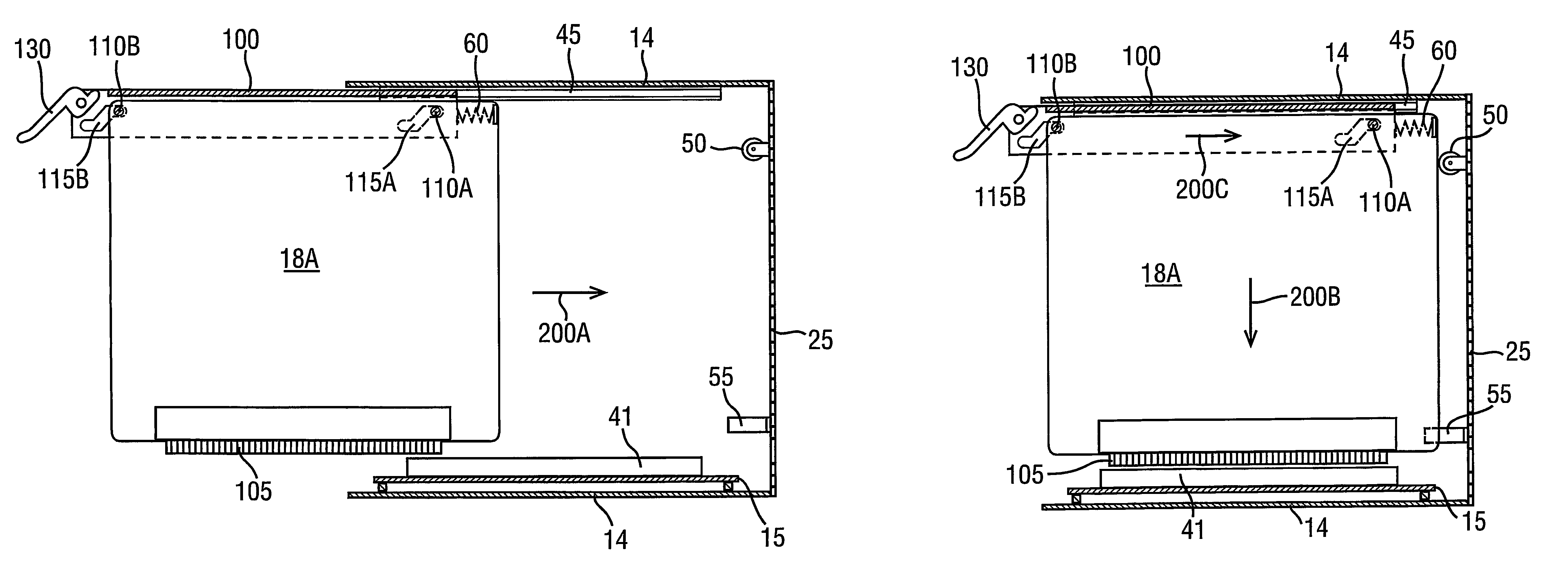
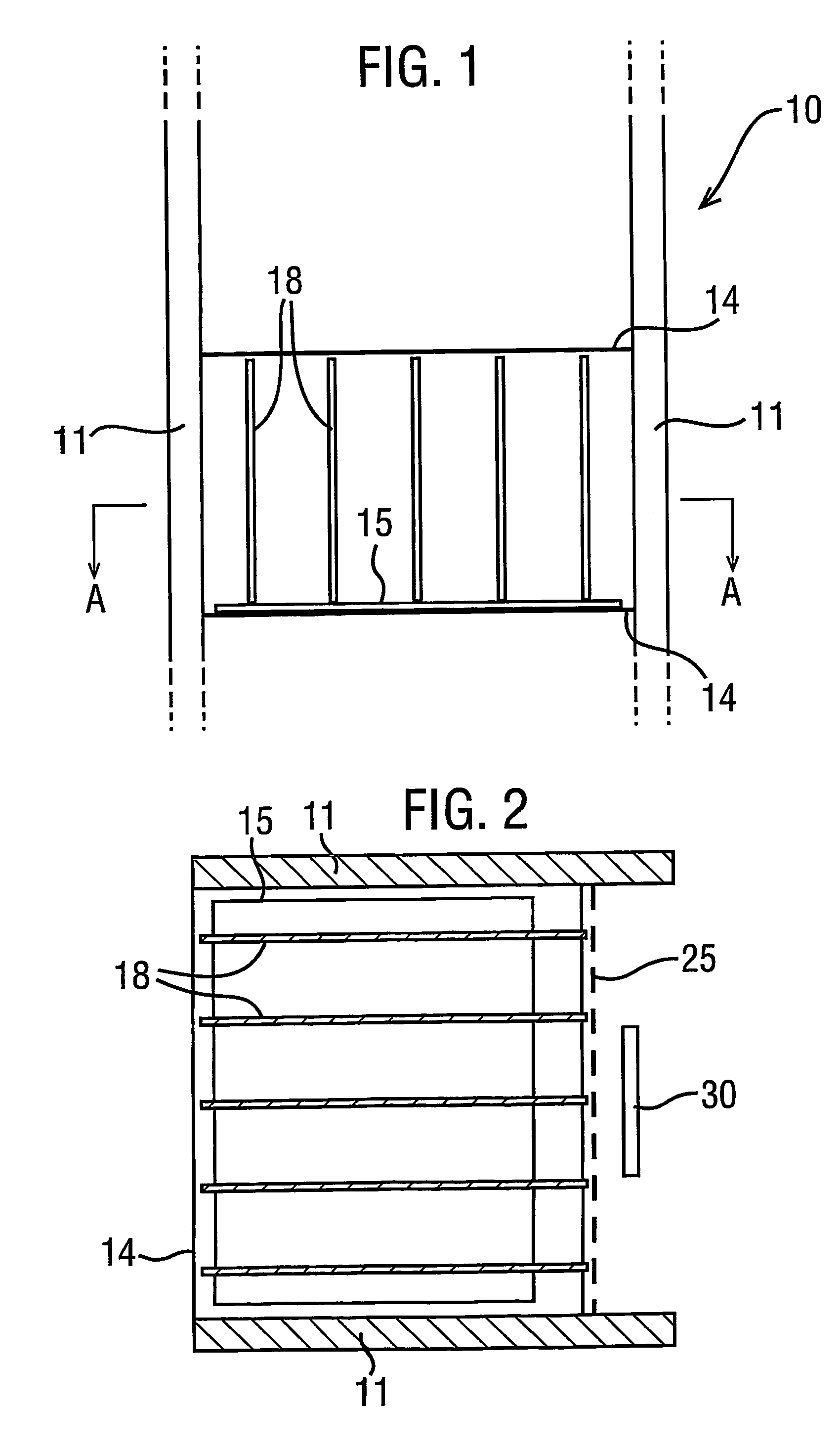
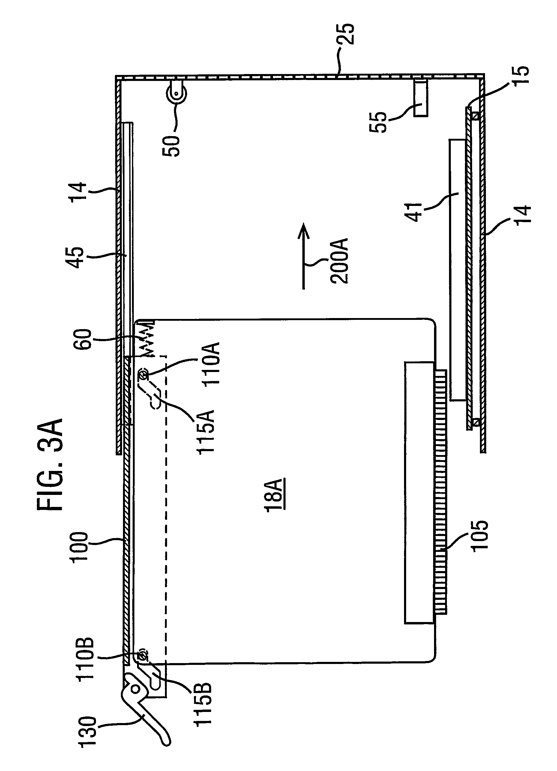
[0025]FIG. 1 illustrates in schematic form the front view of a rack-mounted computer system 10 representing one embodiment of the present invention, in which multiple shelves (or racks) 14 are supported in-between side walls 11. Within each shelf are multiple cards or printed circuit boards (PCBs) 18 that provide computing functionality in accordance with the particular components on the PCB (not shown). These are typically located in predetermined positions on a shelf known as slots. Note that the PCBs within one shelf do not necessarily all provide the same function; similarly the different shelves within system 10 may (and indeed commonly do) vary in purpose and configuration.

[0026]At the base of PCBs 18 is another card 15, which generally provides a bus or other communications facility to interconnect the PCBs 18 on a shelf. Card 15 may include its own processing capability, and may in some implementations also effectively provide the physical structure for shelf 14. In the conf...


PUM


Abstract

A rack-mounted assembly (10) comprises one or more racks, each capable of containing one or more printed circuit boards (PCB) (18), interconnected by a backplane (15) which is located along the bottom of a shelf (14). This position of the backplane (15) allows the rear wall of the rack-mounted assembly to be perforated, thereby permitting a cooling airflow for the PCBs to pass in through the front of the assembly and then out through the back. An insertion mechanism is provided to allow a PCB to be inserted into a rack. To achieve this, the PCB must first travel backwards into the rack-mounted assembly, and then downwards into engagement with the backplane (15). In one embodiment, this is accomplished by supporting the PCB from a hanger (100) which moves in and out of the rack-mounted assembly along a guide rail (45). The hanger includes slots (115) that retain pins (110) from the PCB. The slots are orientated diagonally upwards and backwards. A compression spring (60) is also provided to urge the pins (and hence PCB) forwards. Upon insertion, the hanger moves along guide rail (45) until the PCB abuts a stop (50). At this point further insertion of the hanger forces the pins (110) to move along slots (115) in opposition to spring (60), thereby driving the PCB down into engagement with the backplane (15).

Description

FIELD OF THE INVENTION[0001]The present invention relates to rack-mountable systems, and in particular to the mounting of a card within such a system.BACKGROUND OF THE INVENTION[0002]There is an ongoing demand to provide higher and higher performance for electronic systems, for example computer systems, within racking. Often there is an increase in the heat generated by equipment as the performance of the equipment increases. In order to provide effective cooling, it is necessary to provide paths whereby cooling air can be passed over heat generating components and then be removed from the equipment. In a rack mounted system, it is generally desirable to draw cool air in from the front of the racking and to expel the air warmed by the heat generating components from the rear of the racking.[0003]One common way of providing high performance in a scalable manner is to provide a backplane (e.g. a motherboard) with a plurality of connectors for receiving subsystems (e.g. daughterboards)...

Claims


Application Information

Patent Timeline
Patent Type & Authority Patents(United States)
IPC IPC(8): H05K7/14H05K7/20
CPCH05K7/1409
Inventor WRYCRAFT, SEAN CONOR
Owner ORACLE INT CORP
Why Eureka
Try Eureka