Optical information recording apparatus and method using holography

a technology of optical information and recording equipment, applied in the direction of optical beam sources, instruments, disposition/mounting of heads, etc., can solve the problems of deteriorating information accuracy, difficult to give exposure energy sufficient to record information, and impracticality of using such a pulse laser as described above for light sources

Inactive Publication Date: 2007-05-08
OPTWARE
View PDF31 Cites 31 Cited by
  • Summary
  • Abstract
  • Description
  • Claims
  • Application Information

AI Technical Summary

Benefits of technology

[0025]In the optical information recording method of the invention, the information light and the reference light are applied to the recording medium while it is moving. In the step of moving the irradiating position, the irradiating position of the information light and the reference light is moved to follow a single moving information recording area for a predetermined period. Consequently, the single information recording area keeps be...

Problems solved by technology

When existing photosensitive material for holography is used to make a recording medium for holographic recording and this recording medium is rotated while the recording medium is irradiated with the information light and the reference light that are generated by a semiconductor laser, however, there arises a problem as follows.
That is, in this case, it is difficult to give exposure energy sufficient to record information in the form of an interference pattern to a single information recording area ...

Method used


Image

  • Optical information recording apparatus and method using holography
  • Optical information recording apparatus and method using holography
  • Optical information recording apparatus and method using holography

Examples


first embodiment

[First Embodiment]

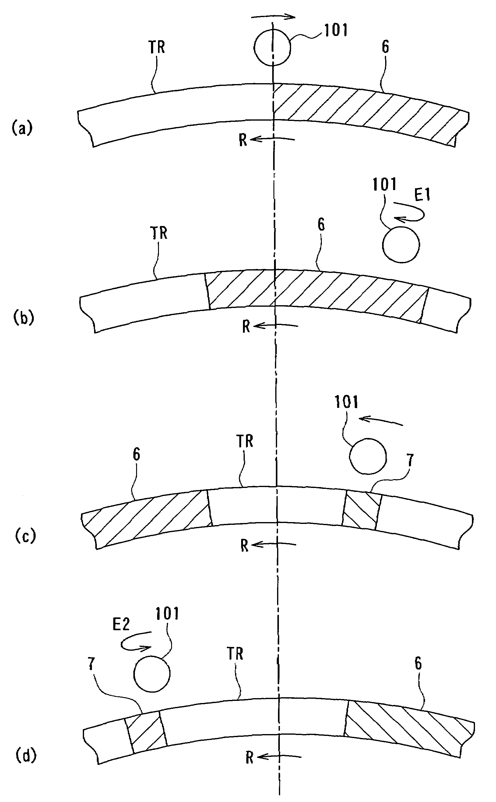
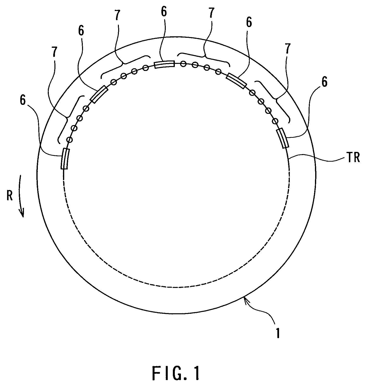
[0066]First, with reference to FIG. 1, an overview will be given of a recording medium 1 used in a first embodiment of the invention. FIG. 1 shows a part of a track of the recording medium 1. The recording medium 1 is disk-shaped and has a plurality of tracks TR. Each of the tracks TR has a plurality of address servo areas 6 arranged at regular intervals. One or more information recording areas 7 are provided between adjacent ones of the address servo areas 6. FIG. 1 shows an example where four information recording areas 7 are arranged at regular intervals between adjacent ones of the address servo areas 6.

[0067]Information for generating a basic clock, i.e., a timing reference for various operations of an optical information recording / reproducing apparatus, information for performing focus servo using a sampled servo system, information for performing tracking servo using the sampled servo system, and address information are recorded in advance in the form of e...

second embodiment

[Second Embodiment]

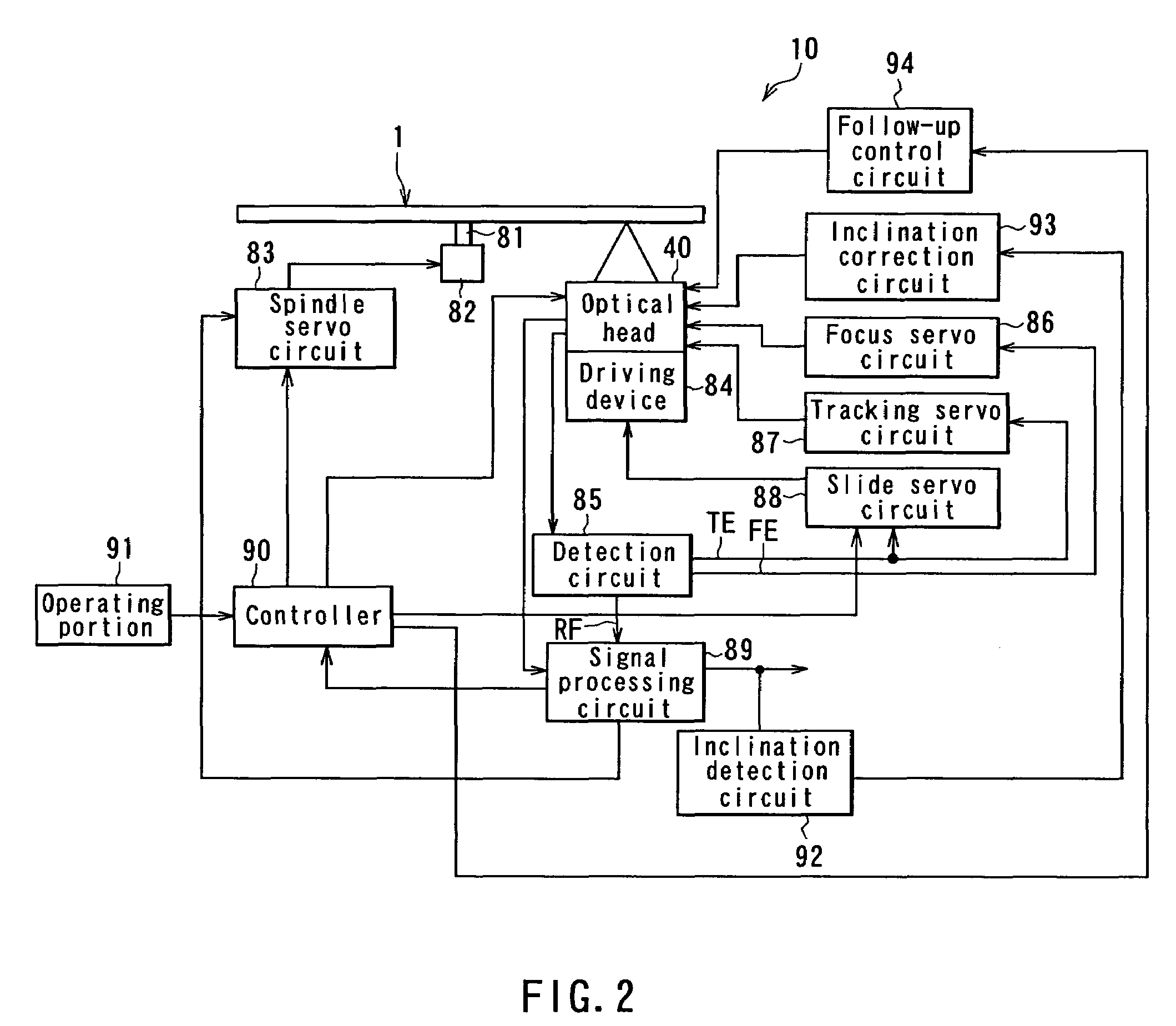
[0181]Next, description will be given of an optical information recording / reproducing apparatus according to a second embodiment of the invention. FIG. 20 is a plan view showing the driving mechanism of an optical head of the optical information recording / reproducing apparatus according to the present embodiment. The present embodiment differs from the first embodiment as to the driving mechanism of the optical head.

[0182]The optical head 40 of the present embodiment has a fixed portion 201, a first movable portion 202, and a second movable portion 203. The fixed portion 201 is fixed to the body of the optical information recording / reproducing apparatus. Two rails 221 extending in a direction of the radius of the recording medium 1 (vertical direction in FIG. 20) are attached to the body of the optical information recording / reproducing apparatus. The first movable portion 202 is supported by the two rails 221 so as to be movable in a direction of the radiu...

third embodiment

[Third Embodiment]

[0190]Next, description will be given of an optical information recording / reproducing apparatus according to a third embodiment of the invention. FIG. 21 is an explanatory diagram showing essential parts of a recording / reproducing optical system of the optical information recording / reproducing apparatus according to the present embodiment.

[0191]First, with reference to FIG. 21, description will given of a configuration of a recording medium according to the present embodiment. The recording medium 301 according to the present embodiment is disk-shaped and has a plurality of tracks, like the recording medium 1 of the first embodiment. Each of the tracks has a plurality of address servo areas 306 arranged at regular intervals. One or more information recording areas 307 are provided between adjacent ones of the address servo areas 306.

[0192]The recording medium 301 comprises two disk-shaped transparent substrates 302 and 304 made of polycarbonate or the like, a...


PUM


Abstract

It is an object of the invention to allow the use of a practical light source to record information in each information recording area of a recording medium having a plurality of information recording areas through the use of holography while moving the recording medium.
When recording information in the information recording areas (7) of the recording medium, the irradiating position (101) of information light and recording-specific reference light is moved such that the irradiating position (101) follows a single moving information recording area (7) for a predetermined period. Consequently, the single information recording area (7) keeps being irradiated with the information light and the recording-specific reference light for the predetermined period. Information is thus recorded in this information recording area (7) in the form of an interference pattern as a result of interference between the information light and the recording-specific reference light.

Description

TECHNICAL FIELD[0001]The present invention relates to an optical information recording apparatus and method for recording information in each information recording area of a recording medium having a plurality of information recording areas through the use of holography.BACKGROUND ART[0002]In general, holographic recording for recording information in a recording medium through the use of holography is performed by superimposing light that carries image information on reference light within the recording medium and by writing a resultingly generated interference pattern into the recording medium. For reproducing the information recorded, the recording medium is irradiated with reference light such that the image information is reproduced through diffraction derived from the interference pattern.[0003]In recent years, volume holography, or digital volume holography in particular, has been developed and is attracting attention in practical fields for ultra-high density optical recordi...

Claims


Application Information

Patent Timeline
IPC IPC(8): G11B7/00G11B7/135G11B7/0045G11B7/0065G11B7/007G11B7/085G11B7/09G11B7/095G11B7/12G11B7/123G11B7/125G11B7/128G11B7/1356G11B7/1374G11B7/1376
CPCG11B7/0065G11B7/08523G11B7/0857G11B7/08582G11B7/123G11B7/128G11B7/1356G11B7/1374G11B7/1376G03H1/12G11B7/00745G11B7/08529G11B7/0901G11B7/0912G11B7/0932G11B7/0933G11B7/0935G11B7/0938G11B7/0956
Inventor HORIMAI, HIDEYOSHI
Owner OPTWARE
Why Eureka
Try Eureka