
Passive sound telemetry system and method and operating toy using the same

a technology of sound telemetry and operating toy, which is applied in the direction of direction/deviation determination system, remote control toy, instruments, etc., can solve the problems of loss and error of time in the rectification process of sound signal and peak value detection process, heighten accuracy, and reduce measurement accuracy, so as to achieve compact measurement equipment

Inactive Publication Date: 2007-05-08
JU SANG GYU
View PDF9 Cites 5 Cited by
  • Summary
  • Abstract
  • Description
  • Claims
  • Application Information

AI Technical Summary

Benefits of technology

[0013]It is another object of the present invention to provide an operating toy having an intelligent and interactive function, for recognizing an acoustic generation position as well as a user command using the passive sound telemetry system and method, and performing various command operations while following the user command.
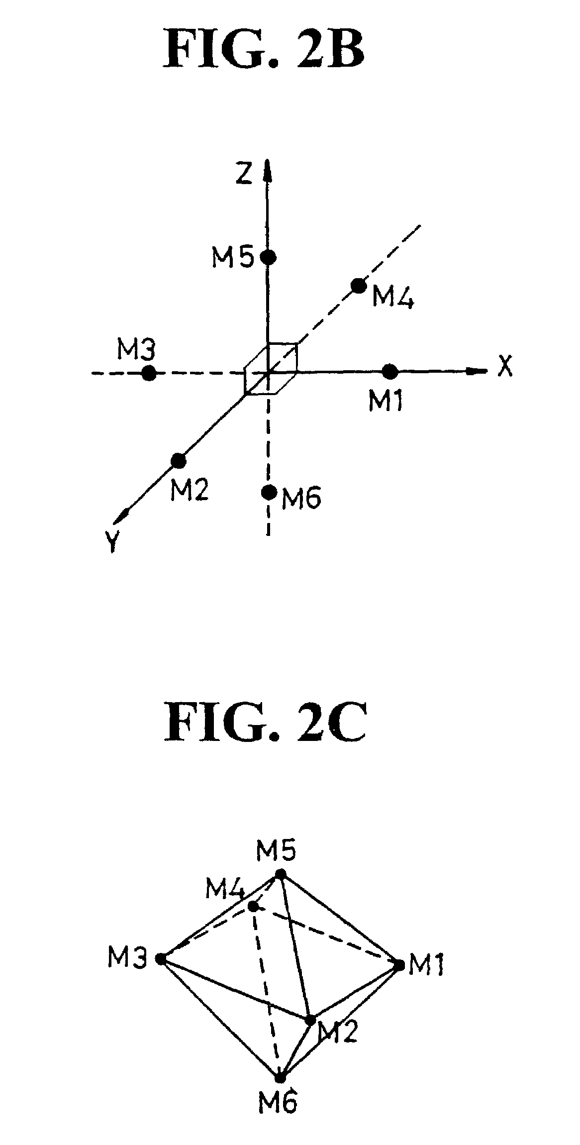
[0020]As described above, the present invention performs calculation of a time difference for every pulse among the sound wave signals of each channel received from three or four sensors disposed in the form of a square on the two-dimensional space, or six sensors disposed in the symmetric tetrahedron form in the three-dimensional space, to thereby enable measurement of the distance and angle with respect to the sound source at a broad direction in real time. Also, a measuring error can be corrected to obtain accurate data by arithmetically averaging the measured values obtained a number of times.
[0021]Also, it is possible to set the interval of the microphones within a wavelength of the sound wave to be measured, in the present invention. Accordingly, a measuring system can be implemented in a small space, to thereby enable measuring equipment to be compact.

Problems solved by technology

First, in view of arrangement of sensors, since a number of sensors are used in matrix in U.S. Pat. No. 4,317,186, and three sensors are aligned in line in U.S. Pat. No. 4,910,719, the distance and angle of the sound source can be measured only within 180 degrees, and since movement of an acoustic source is tracked to calculate a point of generation of an acoustic signal in U.S. Pat. No. 5,586,086, various other problems are revealed.
Thus, in these measuring methods, a loss and error of time may occur in a rectification process of a sound signal and a peak value detection process.
Also, since a high speed measuring for real-time processing does not facilitate, a number of samples cannot be extracted within a short time and thus a correction of a measuring error is limited to thereby lower an accuracy of measurement.
However, they perform an irrelevant operation to a user position.
As described above, the prior art has not proposed a method for obtaining an angle and distance with respect to a sound source in a two-dimensional and / or three-dimensional space at high speed in real time, and correcting a measuring error by using the angle and distance, to thereby not heighten an accuracy of measurement.
Further, the prior art has not proposed an intelligent and interactive operating toy capable of recognizing an angle and distance with respect to a sound source, for example, a user and tracking the user in reply to a call or command of the user, and performing an operation based on the recognized command.

Method used


Image

  • Passive sound telemetry system and method and operating toy using the same
  • Passive sound telemetry system and method and operating toy using the same
  • Passive sound telemetry system and method and operating toy using the same

Examples


Embodiment Construction

[0033]Preferred embodiments of the present invention will be described in more detail with reference to the accompanying drawings.

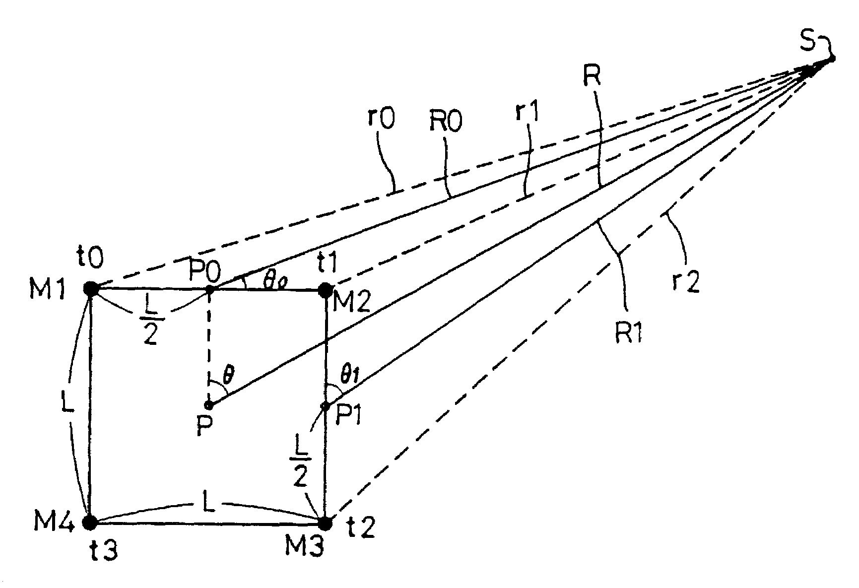
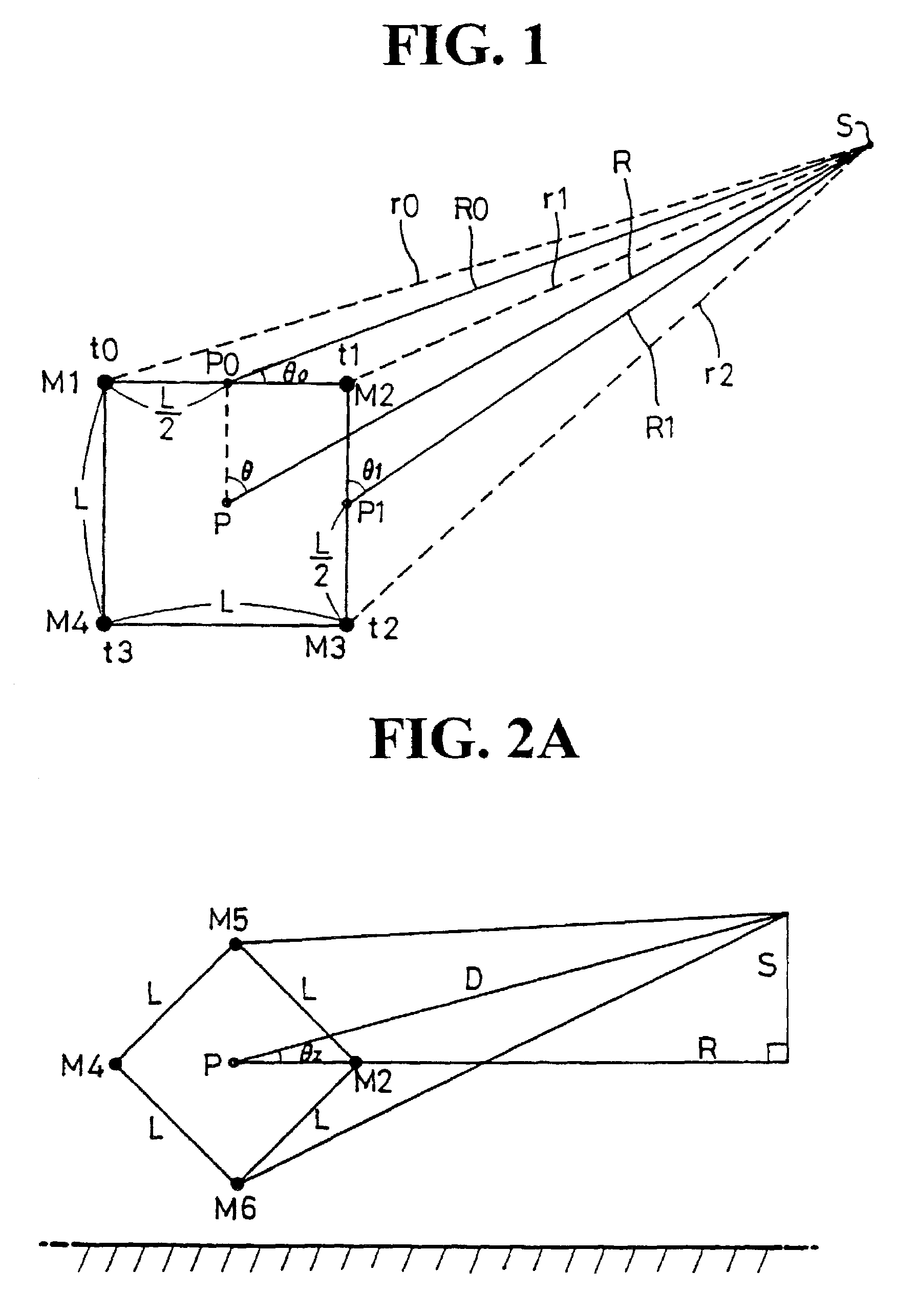
[0034]First, a passive sound telemetry according to the present invention uses a structure where first through fourth microphones M1–M4 as at least three or preferably four acoustic detection sensors are disposed in a square or tetragon preferably, each side of which has a predetermined length L as shown in FIG. 1, when an angle θ and a distance R with respect to a sound source S over 360 degrees from one spot on the two-dimensional space.

[0035]The above disposition of the four first through fourth microphones M1–M4 takes into consideration that the sound wave generated from a sound source S propagates as a substantially circular wave, and thus, an arrival time sequence is determined according to a direction opposing the sound source S in the sound wave reaching the four first through fourth microphones M1–M4, and the sound wave having a relative time dif...


PUM


Abstract

A passive sound telemetry system and method is provided, in which phase differences are calculated for every pulse from acoustic signals received via three or six acoustic receivers, to measure a distance and angle with respect to a sound source. The system is applied to an operating toy giving chase to a user while following the user command. The telemetry system includes first to fourth acoustic receivers (111–114) contained in the housing for receiving first to fourth acoustic signals from a user, first to fourth zero crossing detectors for generating first to fourth pulse signals based on the first to fourth acoustic signals, earliest reception signal detector for detecting a pulse signal having the earliest phase among the first to fourth pulse signals, first to fourth arrival time difference calculator (70) for calculating arrival time differences between the pulse signal of the earliest phase and the first to fourth pulse signals, respectively, thereby obtaining an angle and a distance between the center of acoustic receivers and the user, based on a time difference between the second and third minimum arrival time difference values.

Description

TECHNICAL FIELD[0001]The present invention relates to a passive sound telemetry system and method, and more particularly, to a passive sound telemetry system and method in which phase differences are calculated for every pulse from acoustic signals received via three or six acoustic receivers which are arranged in the shape of a tetragon or a symmetrical tetrahedron, to measure a distance and angle with respect to a sound source which is distant two-dimensionally or three-dimensionally in a broad direction, at high speed in real time, and errors of the measured distance and angle are corrected to obtain an accurate position of the sound source.[0002]Further, the present invention relates to an operating toy having an intelligent and interactive function, for recognizing an acoustic generation position as well as a user command using the passive sound telemetry system and method, and performing various command operations while following the user command.BACKGROUND ART[0003]In general...

Claims


Application Information

Patent Timeline
Patent Type & Authority Patents(United States)
IPC IPC(8): H04R3/00A63H30/04G01S3/808G01S5/22
CPCA63H30/04G01S3/808G01S5/22
Inventor JU, SANG GYU
Owner JU SANG GYU
Learn More