Digital audio precompensation

a digital audio and precompensation technology, applied in the field of digital audio precompensation filter, can solve the problems of affecting the spectral properties of the sound, cumbersome and expensive, and difficult to use in practical use, and achieves the effects of easy handling, good compensation performance, and better control of the extent and amount of compensation

Active Publication Date: 2007-05-08
DIRAC RES
View PDF7 Cites 24 Cited by
  • Summary
  • Abstract
  • Description
  • Claims
  • Application Information

AI Technical Summary

Benefits of technology

[0007]It is a general objective of the present invention to provide an improved design scheme for audio precompensation filters.
[0024]Optimally precompensated audio systems, resulting in superior sound quality and experience.

Problems solved by technology

A system for generating or reproducing sound, including amplifiers, cables and loudspeakers, will always affect the spectral properties of the sound, often in unwanted ways.
Sound reproduction with very high quality can be attained by using matched sets of cables, amplifiers and loudspeakers of the highest quality, but this is cumbersome and very expensive.
Such sub-band solutions will suffer from inadequate phase compensation, which creates problems, in particular at the borders of the bands.
However, all these present methods suffer from significant difficulties, which make their practical use quite problematic.
The design schemes available in prior art generally result in compensation filters that have a high computational complexity and severe practical limitations.
The resulting automatically generated compensation filters are sometimes even dangerous to the audio equipment, due to the risk of generating compensation signals with too high power.

Method used


Image

  • Digital audio precompensation
  • Digital audio precompensation
  • Digital audio precompensation

Examples


Embodiment Construction

[0044]Sections 1–3 describe linear cases, section 4 generalizes the structure and design principle to problems with non-linear and possibly time-varying system models as well as non-linear and possibly time-varying compensators, and section 5 finally describes some implementational aspects.

1. Design for Linear Models and Filters

[0045]For a better understanding of the invention, it may be useful to begin by describing the general approach for designing audio precompensation filters.

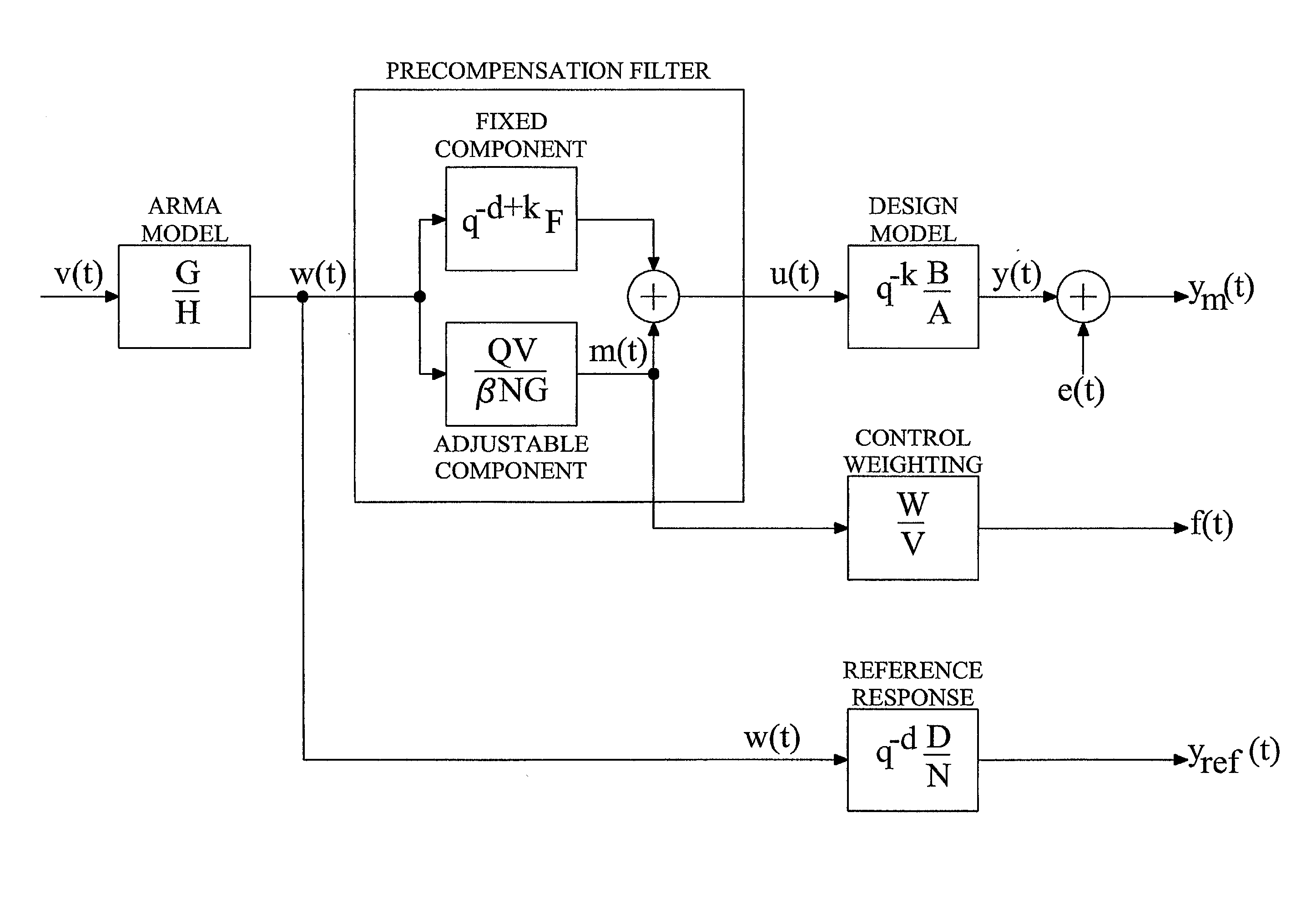
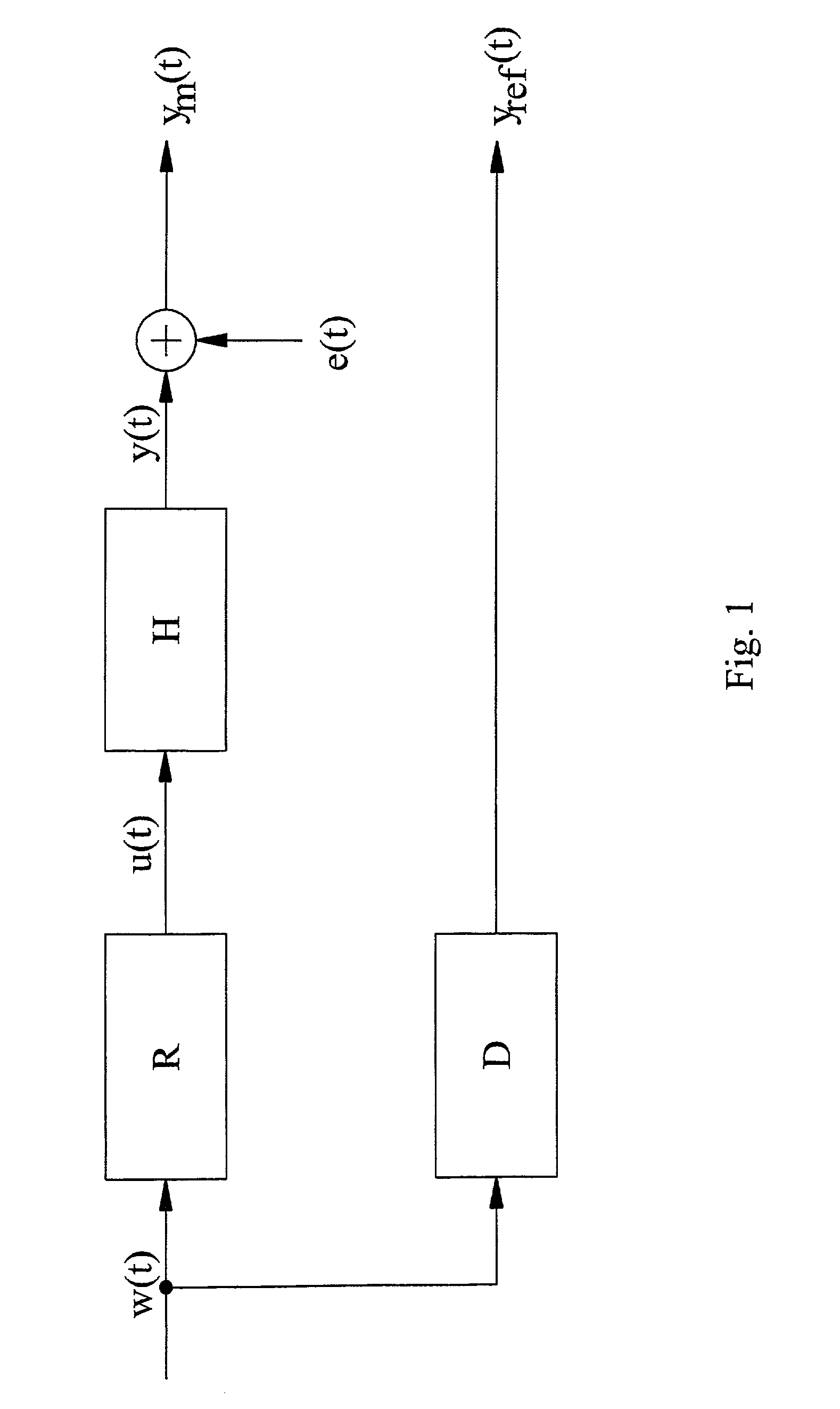
[0046]The sound generation or reproducing system to be modified is normally represented by a linear time-invariant dynamic model H that describes the relation in discrete time between a set of p input signals u(t) to a set of m output signals y(t):

y(t)=Hu(t) ym(t)=y(t)+e(t),  (1.1)

where t represents a discrete time index, ym(t) (with subscript m denoting “measurement”) is an m-dimensional column vector representing the sound time-series at m different locations and e(t) is noise, unmodeled room reflexes, e...


PUM


Abstract

The invention concerns digital audio precompensation, and particularly the design of digital precompensation filters. The invention proposes an audio precompensation filter design scheme that uses a novel class of design criteria. Briefly, filter parameters are determined based on a weighting between, on one hand, approximating the precompensation filter to a fixed, non-zero filter component and, on the other hand, approximating the precompensated model response to a reference system response. For design purposes, the precompensation filter is preferably regarded as being additively decomposed into a fixed, non-zero component and an adjustable compensator component. The fixed component is normally configured by the filter designer, whereas the adjustable compensator component is determined by optimizing a criterion function involving the above weighting. The weighting can be made frequency- and / or channel-dependent to provide a very powerful tool for effectively controlling the extent and amount of compensation to be performed in different frequency regions and / or in different channels.

Description

TECHNICAL FIELD OF THE INVENTION[0001]The present invention generally concerns digital audio precompensation, and more particularly the design of a digital precompensation filter that generates one or several input signals to a sound generating system, with the aim of modifying the dynamic response of the compensated system.BACKGROUND OF THE INVENTION[0002]A system for generating or reproducing sound, including amplifiers, cables and loudspeakers, will always affect the spectral properties of the sound, often in unwanted ways. The reverberation of the room where the equipment is placed adds further modifications. Sound reproduction with very high quality can be attained by using matched sets of cables, amplifiers and loudspeakers of the highest quality, but this is cumbersome and very expensive. The increasing computational power of PCs and digital signal processors has introduced new possibilities for modifying the characteristics of a sound generating or sound reproducing system. ...

Claims


Application Information

Patent Timeline
Patent Type & Authority Patents(United States)
IPC IPC(8): H03G5/00H04R3/04H04R29/00H04S7/00
CPCH04R3/04H04S7/307H04R29/007
Inventor STERNAD, MIKAELAHLEN, ANDERS
Owner DIRAC RES
Why Eureka
Try Eureka