Deblocking and deringing apparatus, program and method

a technology of deringing apparatus and deringing machine, which is applied in the field of deblocking and deringing apparatus, can solve the problems of deteriorating picture quality, blurring noise around the border, and noise generated on parts having a large luminance difference from the surrounding parts, so as to achieve effective screen effect, simplify filter processing, and increase the effect of speed

Inactive Publication Date: 2007-05-08
SEIKO EPSON CORP
View PDF8 Cites 48 Cited by
  • Summary
  • Abstract
  • Description
  • Claims
  • Application Information

AI Technical Summary

Benefits of technology

[0013]Hence, the present invention has been devised in view of the above-described unsolved problems of the conventional technique. The present invention has as its first objective the provision of an image processor and an image processing program, and an image processing method that can simplify filter processing, increase its speed when an image is decoded, and are suitable for realizing effective screen effect. Further, the present invention has as its second objective the provision of an image processor and an image processing program, and an image processing method that are suitable for reducing a memory capacity occupied for computation in filter processing when an image is decoded.

Problems solved by technology

Incidentally, when JPEG or MPEG is adopted, two kinds of noise is generated as will be discussed below and the noise deteriorates picture quality.
Thus, noise is generated on a part having a large luminance difference from the surrounding parts.
In the case of large variations in luminance in a block, for example, when characters exist in the background of a natural picture, harmonic components are removed by DCT from data constituting an original border, resulting in blurred noise around the border.
However, in the first conventional example, since only the border pixels are corrected, distortion of blocks cannot be sufficiently removed.
Further, in VM and the second conventional example, the processing is complicated and calculation load is too heavy.
Moreover, when such techniques are realized by hardware, since the processing is relatively complicated, it is difficult to reduce the size of a circuit.

Method used


Image

  • Deblocking and deringing apparatus, program and method
  • Deblocking and deringing apparatus, program and method
  • Deblocking and deringing apparatus, program and method

Examples


first embodiment

[0172]Described below is the operation of the present invention.

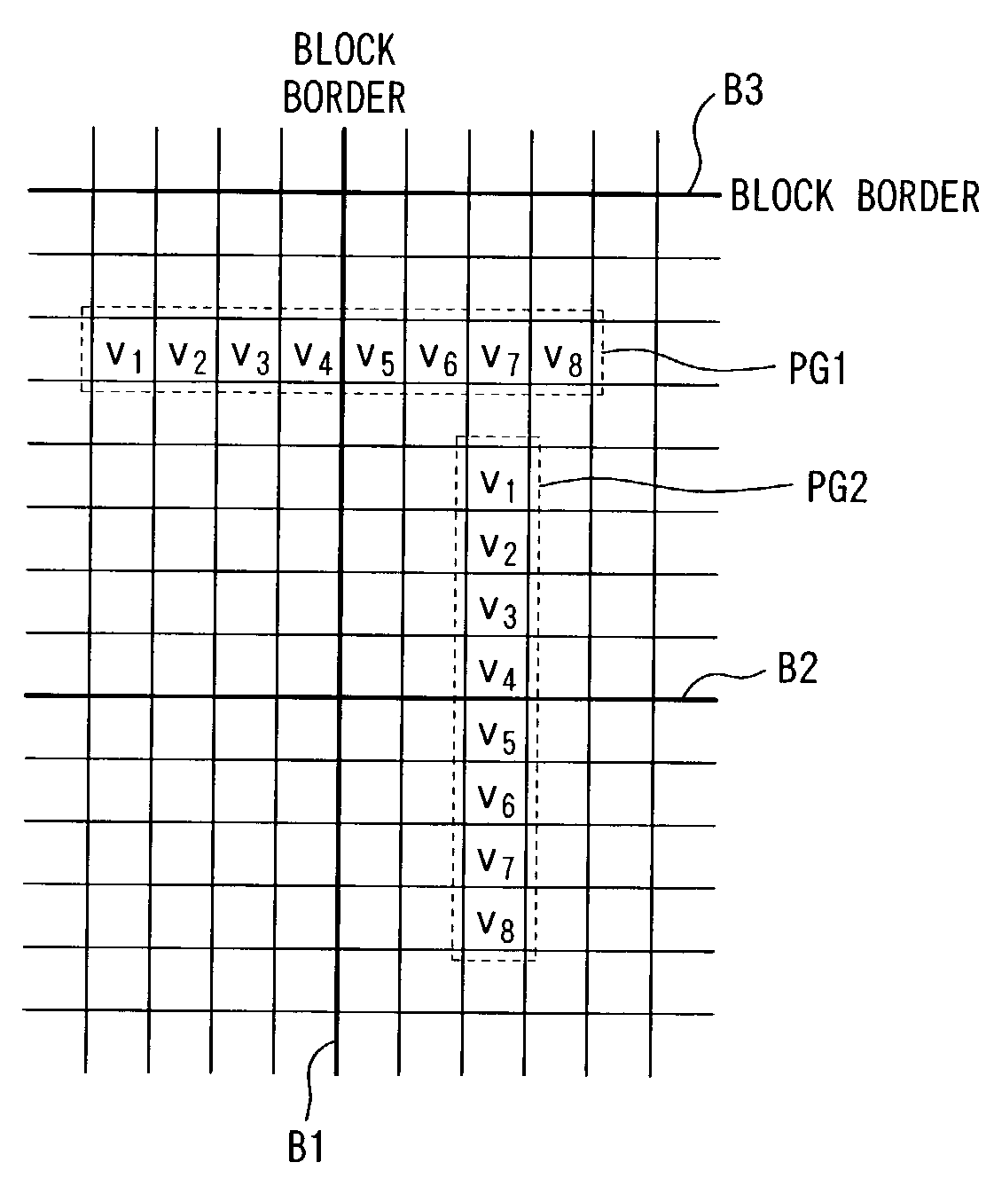
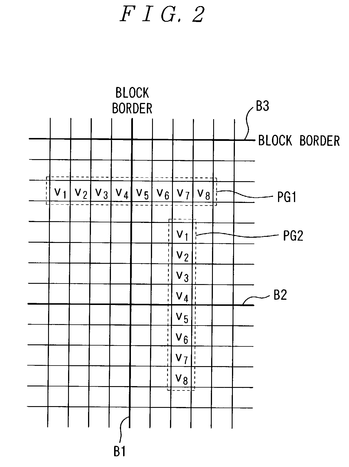
[0173]First, the case in which the deblock filter processing is performed is described below by referring to an example of performing the deblock filter processing on each pixel of the pixel array PG1 shown in FIG. 1.

[0174]When the deblock filter processing is performed on each pixel of the pixel array PG1, the processes in steps S100, S102, S200, and S202 are first performed, and then the address of the pixel array PG1 in the area of the upper right portion of the block is computed, the pixel data required in the operation in the horizontal direction and the pixel data required in the operation in the vertical direction in the pixel array PG1 are collectively read to the buffer according to the computed address of the pixel array PG1. Since the pixel array PG1 is in the third row from the top, the pixel data including a total of 17 pixels, that is, the four right-to-left contiguous pixels from the upper right pixel in...

second embodiment

[0229]The operations are described below by referring to FIGS. 12 and 13. FIG. 12 shows the case in which the pixel values v1 to v8 are rearranged for operations. FIG. 13 is a bar graph showing the value of each pixel of the pixel array PG1.

[0230]First, the deblock filter processing is described below by referring to an example of performing the deblock filter processing on each pixel of the pixel array PG1 shown in FIG. 1.

[0231]When the deblock filter processing is performed on each pixel of the pixel array PG1, the processes in steps S200, S202, S230 to S238 are performed, the necessary pixel data for the operations in the horizontal direction and the necessary pixel data for the operations in the vertical direction relating to the pixel array PG1 are collectively read to the buffer according to the address of the pixel array PG1, and the pixel values v1 to v5 are read to s(0) to s(4) respectively as shown in FIG. 12(A).

[0232]After step S500, it is determined whether or not the d...

third embodiment

[0263]The operations are described below by referring to FIGS. 17. FIG. 17 is a bar graph showing the value of each pixel of the pixel array PG1.

[0264]First, the deblock filter processing is described below by referring to an example of performing the deblock filter processing on each pixel of the pixel array PG1 shown in FIG. 1.

[0265]When the deblock filter processing is performed on each pixel of the pixel array PG1, the processes in steps S200, S202, S260 to S268 are performed, the necessary pixel data for the operations in the horizontal direction and the necessary pixel data for the operations in the vertical direction relating to the pixel array PG1 are collectively read to the buffer according to the address of the pixel array PG1, and the pixel values v1 to v5 are read to s(4) to s(0) respectively as shown in FIG. 12(B).

[0266]After step S530, it is determined whether or not the deblock filter processing is performed for s(1). That is, if the absolute value of the difference...


PUM


Abstract

An image processor is provided which simplifies filter processing and increases the speed when an image is decoded, and is suitable for realizing effective screen effect.
In deblocking filter processing, as to a pixel array intersecting a boundary between adjacent blocks, pixel values v2′ to v7′ after filtering are computed by filter arithmetic equations as shown below
v2′=(v2+v5)/2+(v2−v5)/4
v3′=(v3+v5)/2+(v3−v5)/8
v4′=(v4+v5)/2
v5′=(v5+v4)/2+(v5−v4)/8
v6′=(v6+v4)/2+(v6−v4)/4
v7′=(v7−(v7−v4)/8.

Description

BACKGROUND OF THE INVENTION[0001]1. Field of the Invention[0002]The present invention relates to a processor, a program, and a method for performing filter processing on an expanded image when images are expanded in the unit of blocks based on compressed image data which is compressed in JPEG (Joint Photographic Coding Experts Group) or MPEG (Moving Picture Experts Group) and so on, and particularly concerns an image processor, an image processing program, and an image processing method that can simplify filter processing and increase its speed when an image is decoded, and are suitable for an effective screen effect.[0003]2. Description of the Related Art[0004]JPEG has been widely known as compressing technique for a static image, and MPEG has been widely known as compressing technique for a moving image. In such image compressing methods, a block of 8×8 pixels is used as one unit and DCT (Discrete Cosine Transform) is performed. DCT is processing for decomposing an original image ...

Claims


Application Information

Patent Timeline
Patent Type & Authority Patents(United States)
IPC IPC(8): G06K9/40G06T5/20G06T5/00H04N1/409H04N1/41H04N19/117H04N19/134H04N19/136H04N19/176H04N19/196H04N19/423H04N19/426H04N19/60H04N19/625H04N19/80H04N19/86
CPCH04N19/527H04N19/86G06T5/20G06T5/002G06T2207/10024
Inventor MIURA, HIROTSUNAISHIKAWA, MASAKI
Owner SEIKO EPSON CORP
Why Eureka
Try Eureka