Control loop for switching power converters

a power converter and control loop technology, applied in the direction of power conversion systems, dc-dc conversion, instruments, etc., can solve the problems of system instability in a closed loop configuration, error amplifiers, and inability to produce stable controllers, and achieve simple voltage comparators, promote stability in the loop, and simple filters to linearize the nonlinear response of the comparator

Inactive Publication Date: 2011-05-10
AIVAKA
View PDF33 Cites 19 Cited by
  • Summary
  • Abstract
  • Description
  • Claims
  • Application Information

AI Technical Summary

Benefits of technology

[0020]The above object has been satisfied with a control loop for a SPC that uses a bridge rectifier to provide rectified DC to a filter loop having a simple voltage comparator instead of a traditional operational amplifier, along with a simple filter to linearize nonlinear response of the comparator. The filter has poles and zeros offsetting the poles and zeros of the bridge rectifier to promote stability in the loop. The new circuit can tolerate process, temperature and voltage variations, and is capable of operating with reduced power supply voltage with no degradation in performance. The circuit can easily be ported into different technologies without major design modifications. The circuit can be applied to any SPC circuit including DC-DC, DC-AC and AC-DC converters. By using this new regulation circuit the power supply voltage applied into the SPC can easily be lowered without harming regulated Vout.

Problems solved by technology

Now, since there are two poles within the regulation loop, this system would be unstable in a closed loop configuration if there is no change made to the loop.
One of the main problems in a regulation loop is the error amplifier itself.
If the voltage gain or speed of the error amplifier is compromised for any reason, then additional error terms are introduced, which in turn may not produce a stable controller.
So, performance of the error amplifier is a very crucial and important issue that must be considered for any regulator.
Thus, the minimum voltage for power source or (Vin) is often limited to around 2V for a conventional buck SPC.
So, if value of Vin drops below this critical limit of around 2V then error amplifier that is used in the buck SPC regulation loop could have a reduced voltage gain or bandwidth, which could hinder the performance of the entire converter, or may prevent operation of the converter.
Thus, general use of an architecture similar to that shown in FIG. 1 in buck SPCs is limited mainly to system where Vin is, at a minimum, around 2V.
Thus, linear regulator are considered very inefficient for large voltage drops and may not be suitable for a system where Vin=1.3V and Vout=0.65V, since η=50%.
Such an approach would need two sets of SPCs which increases the cost and would reduce the entire efficiency of power converter circuitry.
The cost of the die was fairly large.

Method used


Image

  • Control loop for switching power converters
  • Control loop for switching power converters
  • Control loop for switching power converters

Examples


Embodiment Construction

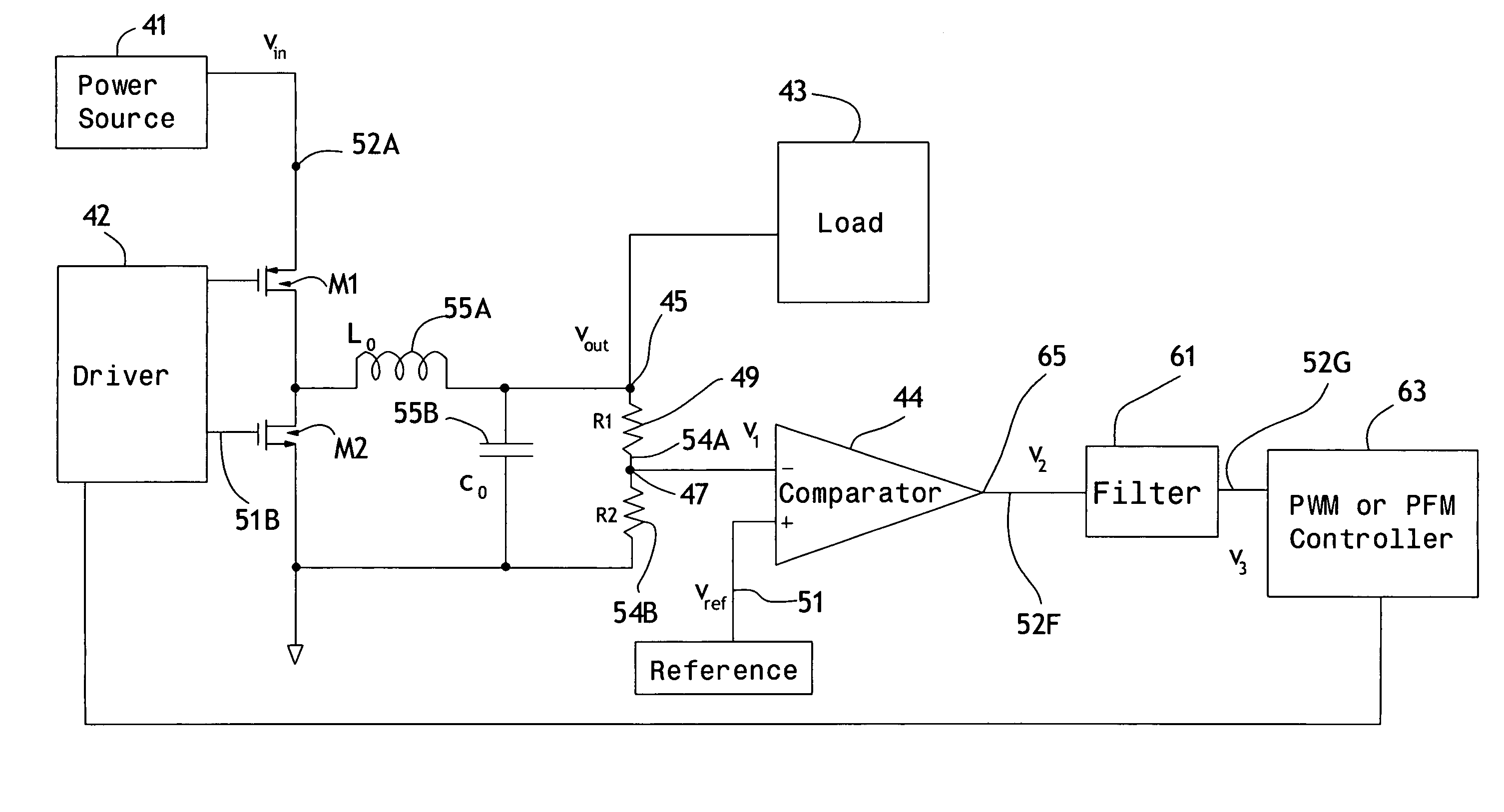
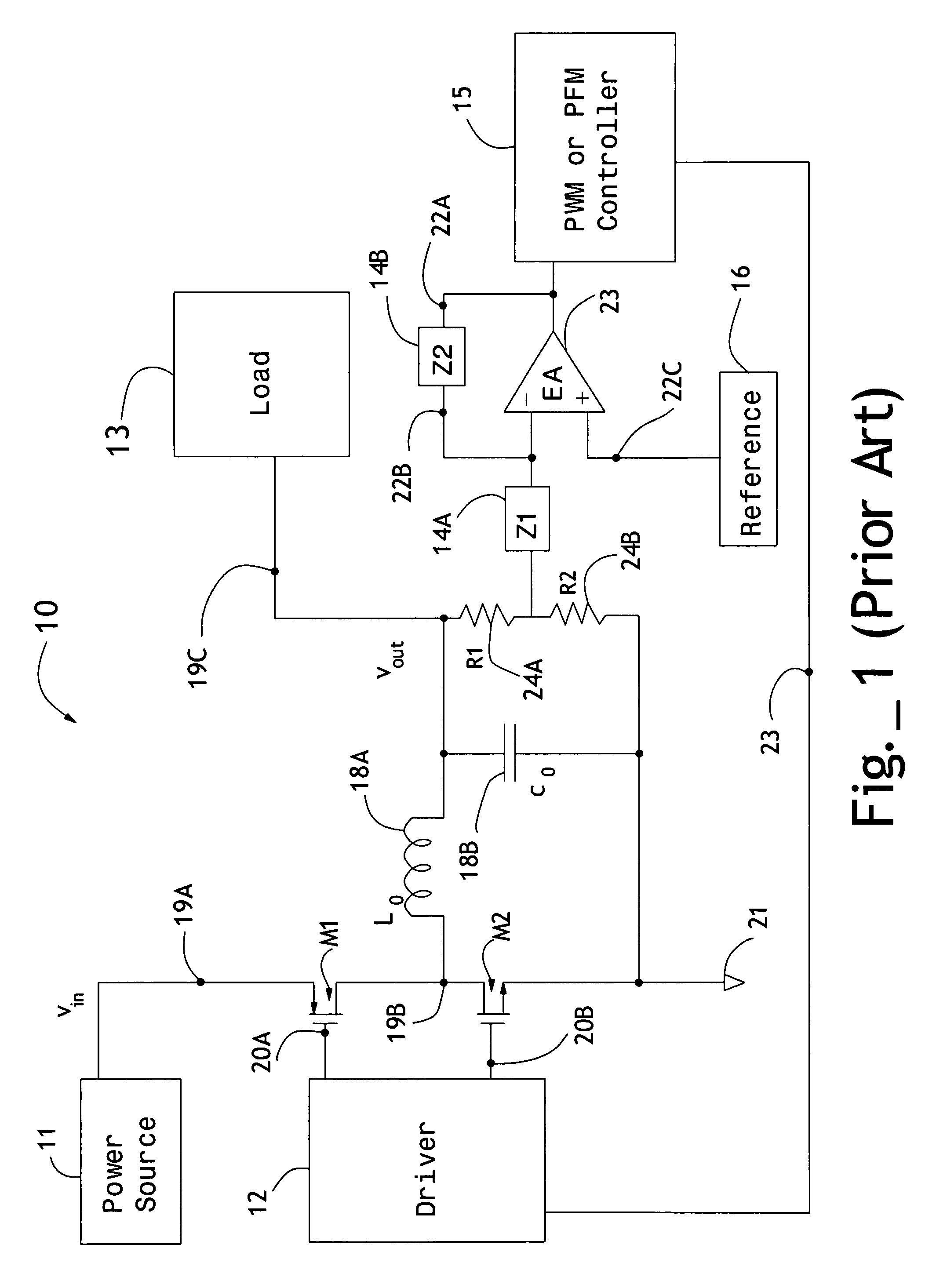
[0031]With reference to FIG. 4, the present invention came about with the realization that the function of the linear error amplifier 23 in FIG. 1 and the compensation loads Z1 and Z2 can be replaced with a simple high gain detection circuit with a non-linear response, and a proper filter to create a pseudo linear behavior to regulate the loop. At very low frequencies near DC, the error amplifier behaves like a simple voltage comparator with a very large voltage gain. Yet, it is only at higher frequencies that it can assist in compensating the loop. So, the same behavior can be implemented with components that may not suffer from shortcomings of typical error amplifiers. A non-linear detection circuit such as a voltage comparator is typically more robust to variations in headroom voltage, temperature, and process variations. Hence, its adaptability to these changes can be used to make the entire compensation loop more robust.

[0032]A high gain voltage comparator 44 is used to detect ...


PUM


Abstract

A pulse regulation loop for a clocked switching power converter where the loop is around a bridge converter. The loop features a comparator, a charge pump and a filter in series, feeding a pulse modulator controlling the clock duty cycle of the bridge. Ripple in the bridge converter output is feed to the comparator which causes the charge pump to inject or remove charge from the filter at the clock rate providing control over the modulator that establishes converter efficiency. The charge pump is of the PLL type, having switches responsive to voltage output from the comparator, evaluating the converter ripple relative to a reference voltage.

Description

FIELD OF INVENTION[0001]This invention relates generally to voltage regulation of switching power converters.BACKGROUND OF INVENTION[0002]Switching power converters (SPCs) are widely used in electronic systems to convert a direct current (DC) voltage into a different DC voltage, or an alternating current (AC) voltage into a DC voltage, or a DC voltage into an AC voltage. SPCs are widely used in both portable and non-portable applications for a wide range of power and voltage ranges. There are numerous architectures for each application such as buck (step down), boost (step up), H-bridge, and fly back. Yet, regardless of the type of converter, they all need a controller so that a regulated and well maintained voltage at the output is created. The generated output voltage is often used as a power supply to an specific load within the electronic system. There could be different types of SPCs in one system, each with its own particular load and controller and its particular set of speci...

Claims


Application Information

Patent Timeline
Patent Type & Authority Patents(United States)
IPC IPC(8): G05F1/575G05F1/656H02M3/156
CPCH02M3/156G05F1/44
Inventor DOWLATABADI, AHMAD B.
Owner AIVAKA
Why Eureka
Try Eureka