Clock generation system

a clock generation and clock technology, applied in the direction of generating/distributing signals, pulse techniques, instruments, etc., can solve the problems of deterioration of s/n ratio, high cost of clock generation system approach, and limited s/n ratio of pll circuit, etc., to achieve sufficient s/n ratio and minimize the influence of noise floor

Active Publication Date: 2007-05-08
ROHM CO LTD
View PDF4 Cites 65 Cited by
  • Summary
  • Abstract
  • Description
  • Claims
  • Application Information

AI Technical Summary

Benefits of technology

[0031]In view of the fact that the S / N ratios of the PLL circuits are improved according to the frequency division ratio and lowered according to the multiplication ratio, and that it is limited by the S / N ratio of the noise floor, the invention generates a common intermediate-frequency clock in the first PLL circuit and the intermediate-frequency clock is supplied to the second and the third PLL circuits. This permits elimination of the limitation, or reduction of the influence, of the noise floor on the S / N ratio. Thus, in spite of the noise floor limitation on the S / N ratios, a second and a third-frequency clocks can be generated from a first-frequency clock with sufficient S / N ratios.
[0032]Furthermore, the inventive clock generation system can generate a first 27 MHz reference clock series for a video system, a second 33.8688 MHz reference clock series for a sound system (particularly for CD) (with the frequencies being integral multiples of a 44.1 kHz sampling frequency), and a third 36.864 kHz reference clock series for another sound system (particularly for DVD) (with the frequencies being integral multiples of 48 kHz and 32 kHz sampling frequencies), all with sufficient S / N ratios.
[0033]The use of a common reference clock adequate for the first through third-frequency clocks eliminates the limitation or minimizes the influence of the noise floor, thereby allowing generation of the first through the third-frequency clocks having sufficient S / N ratios.

Problems solved by technology

However, this approach is costly for a clock generation system because it requires one oscillation module for each of the required reference clock frequencies.
It should be noted, however, that since a PLL circuit is in operation on the noise floor of a given IC (integrated circuit) on which the PLL circuit is formed, the S / N ratio of the PLL circuit is limited by the S / N ratio of the noise floor.
This deterioration in S / N ratio is a problem that must be solved, since DVD systems, etc. in general requires a S / N ratio of at least 50 [dB], preferably more than 60 [dB].

Method used


Image

  • Clock generation system
  • Clock generation system
  • Clock generation system

Examples


first embodiment

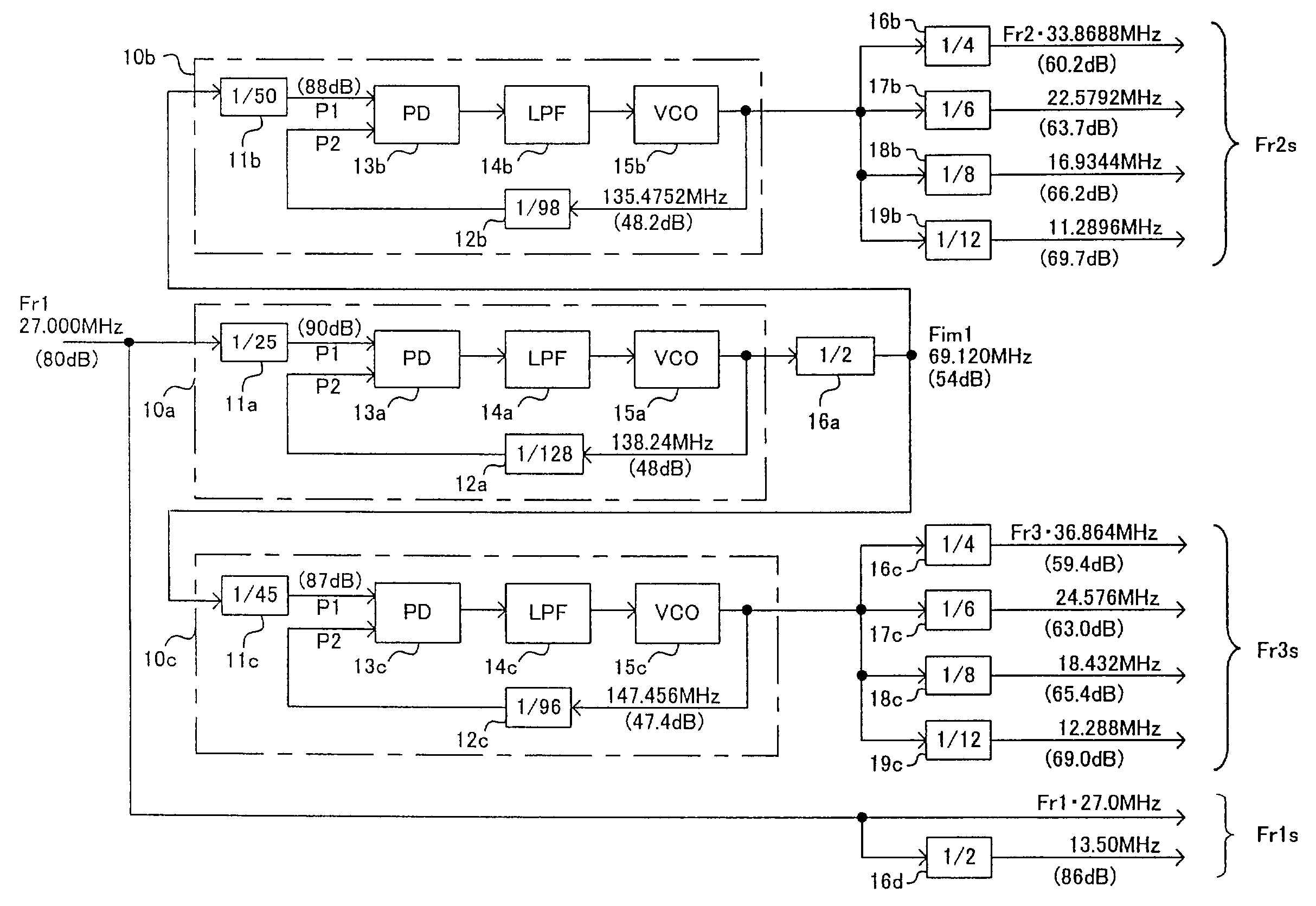
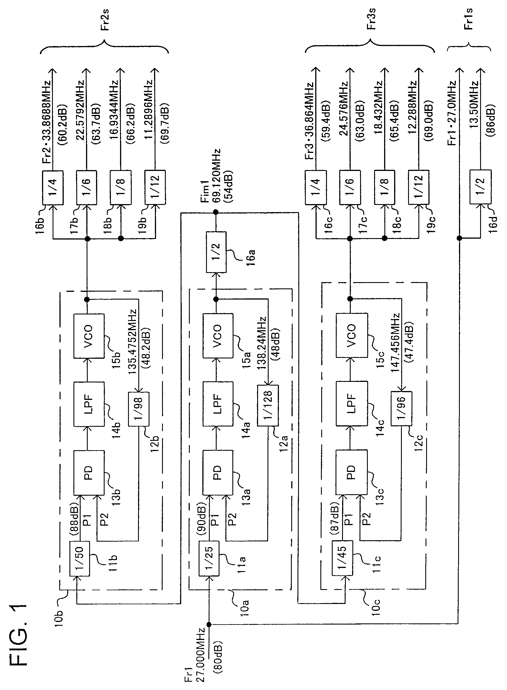
[0043]Referring to FIG. 1, there is shown in block diagram a clock generation system according to the invention. This clock generation system is designed to receive as a reference clock a first reference frequency clock of 27 MHz for use in a video system to generate clocks of a first frequency series (or 27 MHz series) for video system, a second reference frequency series (or 33.8688 MHz series) for audio system (particularly for CD), and a third reference frequency series (or 36.864 MHz series) for audio system (particularly for DVD).

[0044]In view of the fact that the S / N ratio of a PLL circuit gets improved by the frequency division ratio thereof, lowered by the multiplication ratio, and limited by the S / N ratio of the noise floor, a first-frequency clock Fr1 is supplied as the reference clock to a first PLL circuit 10a, which generates an intermediate-frequency clock Fim1 having a frequency as determined by the first reference frequency clock Fr1 and a first predetermined ratio....

second embodiment

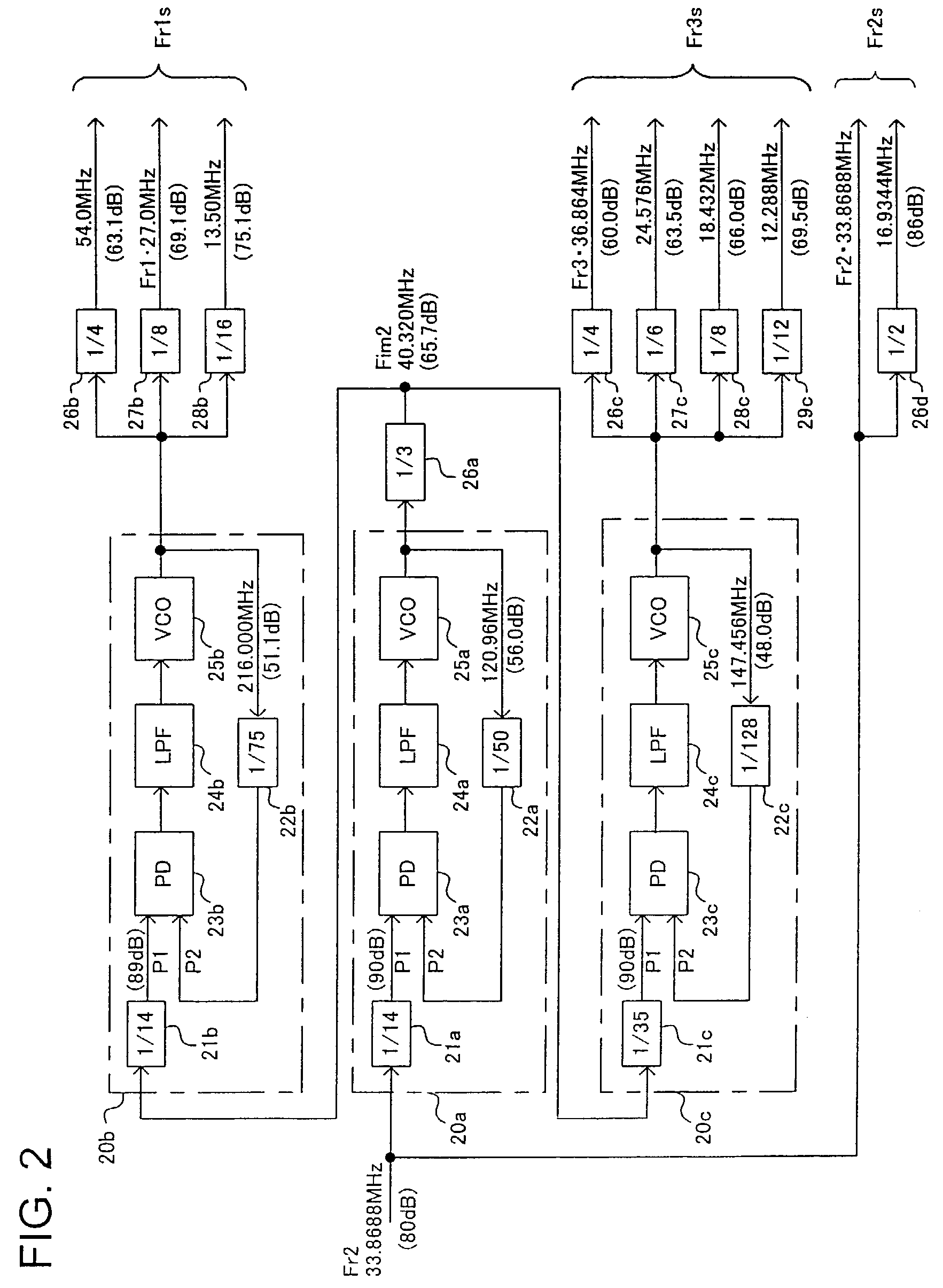
[0064]Referring to FIG. 2, there is shown a structure of a clock generation system in accordance with the invention.

[0065]In the clock generation system shown in FIG. 2, the first PLL circuit 20a is supplied with the second reference frequency clock Fr2 (33.8688 MHz). Based on this second reference frequency clock Fr2, clocks of the first reference frequency series Fr1s including the first reference frequency clock Fr1 and clocks of a third reference frequency series Fr3s including a third reference frequency clock Fr3 are generated. Although the first through the third PLL circuits 20a, 20b, and 20c and the respective frequency dividers have different frequencies and division ratios, they are the same in fundamental structure and function as the first embodiment shown in FIG. 1.

[0066]The first frequency divider 21a of the first PLL circuit 20a divides the input clock Fr2 by a factor of 14, and supplies the resultant clock to one comparative input P1 of the PD 23. The S / N ratio of t...

third embodiment

[0079]Referring to FIG. 3, there is shown a structure of a clock generation system in accordance with the invention. The clock generation system shown in FIG. 3 receives as its reference clock a 36.864 MHz third reference frequency clock for sound system (especially for DVD) and outputs clocks of the first 27 MHz reference frequency series for video system and clocks of a second 33.8688 MHz reference frequency series for audio system (especially for CD).

[0080]In this clock generation system of FIG. 3 the third reference frequency clock Fr3 (36.864 MHz) is supplied to the first PLL circuit 30a. Based on the third reference frequency clock Fr3, clocks of a first reference frequency series Fr1s that includes the first reference frequency clock Fr1 and clocks of a second reference frequency series Fr2s that includes the second reference frequency clock Fr2 are generated. It is noted that the first through third PLL circuits 30a, 30b, and 30c and the frequency dividers included in this e...


PUM

PropertyMeasurementUnit
frequenciesaaaaaaaaaa

Abstract

A clock generation system for generating a first-, a second-, and a third-reference frequency clocks having respective frequencies having predetermined ratios to the reference frequency of a reference clock, using PL circuits in such a way that the clocks have sufficient S / N ratios in spite of the S / N ratio limitation by the noise floor. A first reference frequency clock is supplied to a first PLL circuit to generate an intermediate-frequency clock having an intermediate frequency having a predetermined ratio to the reference clock. The intermediate-frequency clock is supplied to a second and a third PLL circuits to generate a second and a third reference frequency clocks having frequencies respectively having a second and a third ratios to the intermediate frequency, respectively.

Description

FIELD OF THE INVENTION[0001]The invention relates to a clock generation system for generating from a given frequency clock a first-reference frequency clock, a second-reference frequency clock, and a third-reference frequency clock respectively having frequencies having predetermined ratios to the frequency of the given clock. More particularly, the invention relates to a clock generation system suitable for generating a multiplicity of clocks having reference frequencies required by a DVD (Digital Versatile Disc) system.BACKGROUND OF THE INVENTION[0002]In the art of DVD system that utilizes, for example, a DVD player, a DVD-R, and a DVD-RW, it is necessary to provide a multiplicity of clocks of different reference frequencies (referred to as reference frequency clocks), including at least a 27 MHz clock series (first reference frequency series) for a video system, a 33.8688 MHz clock series (second reference frequency series) for a sound system (particularly CD) (the series includi...

Claims


Application Information

Patent Timeline
Patent Type & Authority Patents(United States)
IPC IPC(8): G06F1/04G06F1/06G06F1/10H03B19/12H03K21/00H03K23/00H03K3/03H03L7/16H03L7/18G11B20/14H03L7/087H03L7/22H03L7/23
CPCG06F1/06G11B20/1403H03L7/23
Inventor FUJIWARA, MASAYUONISHI, MASAKI
Owner ROHM CO LTD
Why Eureka
Try Eureka