Method and apparatus for controlled force deployment of user interface devices

a user interface and deployment method technology, applied in the direction of mechanical pattern conversion, instruments, transportation and packaging, etc., can solve the problems of inadvertent pressure on innocent passengers, potential harm to human life and limb, and passenger injuries, so as to reduce the amount of power

Active Publication Date: 2007-05-08
BURRANA IP & ASSETS LLC
View PDF11 Cites 10 Cited by
  • Summary
  • Abstract
  • Description
  • Claims
  • Application Information

AI Technical Summary

Benefits of technology

[0016]According to one alternative embodiment, the present invention further comprises an actuator that may cause the deployable member of the device to move from a stowed position to a deployed position. An actuator control unit further comprises the invention and in one embodiment applies power to the actuator in order to cause the user interface assembly to move out of the stowed position. The actuator control unit may further reverse the power applied to the actuator if it detects that the rate-of-motion as indicated by the motion sensor fails to meet a first pre-established threshold. Once the user interface assembly has traveled at this minimum rate-of-motion for a pre-established interval of time, the actuator control unit may increase the power that it applies to the actuator. This pre-established interval of time is typically referred to as a “clearance interval”. Increasing the power level may allow for rapid movement of the user interface assembly into its fully deployed position. Typically, the actuator control unit reduces the amount of power that it applies to the actuator to a holding level once full deployment is achieved.
[0017]According to one alternative embodiment of the present invention, the actuator control unit may reverse the power that it applies to the actuator if it detects, based on motion information provided by the motion sensor, that the deployable member has been moved away from its fully deployed position by a pre-established amount. This may cause the deployable member to be retracted back into a stowed position.

Problems solved by technology

The aircraft industry has long used retractable user interface devices because of the limited operational space that is available either in the cockpit or in the passenger compartment of an aircraft.
Even some stereo systems meant for use in cars may comprise deployable keyboards because of the limited amount of space available on the console for conventional controls.
However, as with any mechanized assembly, there exists the potential to harm human life and limb.
If allowed to operate in this type of an unrestrained fashion, deployment of a user interface assembly may inadvertently apply harmful pressure to an innocent bystander.
One such situation is commonly encountered in an aircraft application of an overhead display; a passenger inadvertently collides with the deployed display screen comprising the display assembly.
In this case, it is likely that the passenger will sustain physical injury if the fully deployed position is rigidly maintained.

Method used


Image

  • Method and apparatus for controlled force deployment of user interface devices
  • Method and apparatus for controlled force deployment of user interface devices
  • Method and apparatus for controlled force deployment of user interface devices

Examples


Embodiment Construction

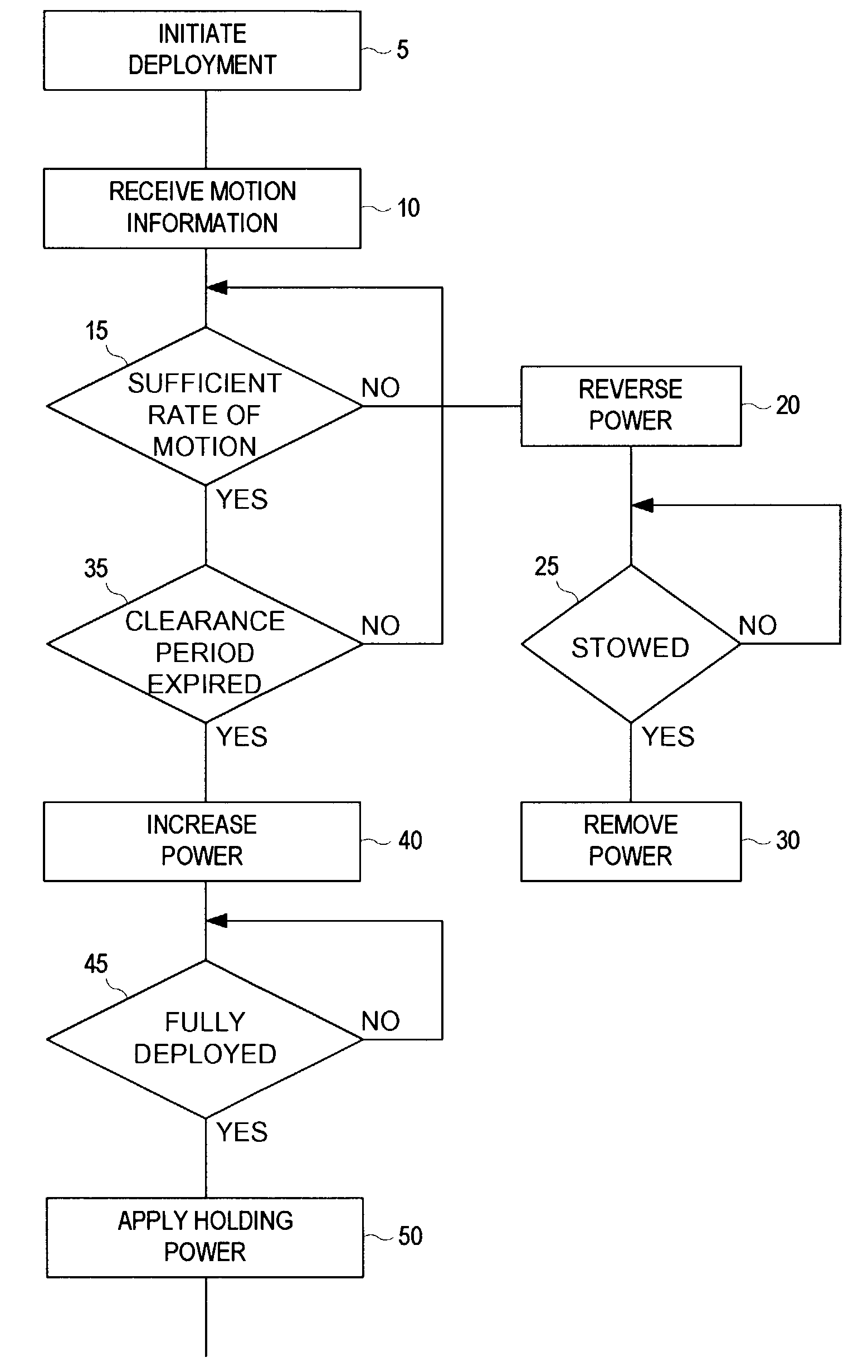
[0029]The present invention comprises a method for deploying a deployable user interface according to a controlled force profile. The present invention also comprises an apparatus that embodies the methods taught herein. When a deployable device is automatically deployed from it's housing, it may be beneficial to initiate deployment with a modest amount of force in order to ensure that obstructions that may be present in the deployment path are not injured or harmed. Typically, this may be accomplished by reducing the amount of force that may be applied to the deployable member when deployment first starts.

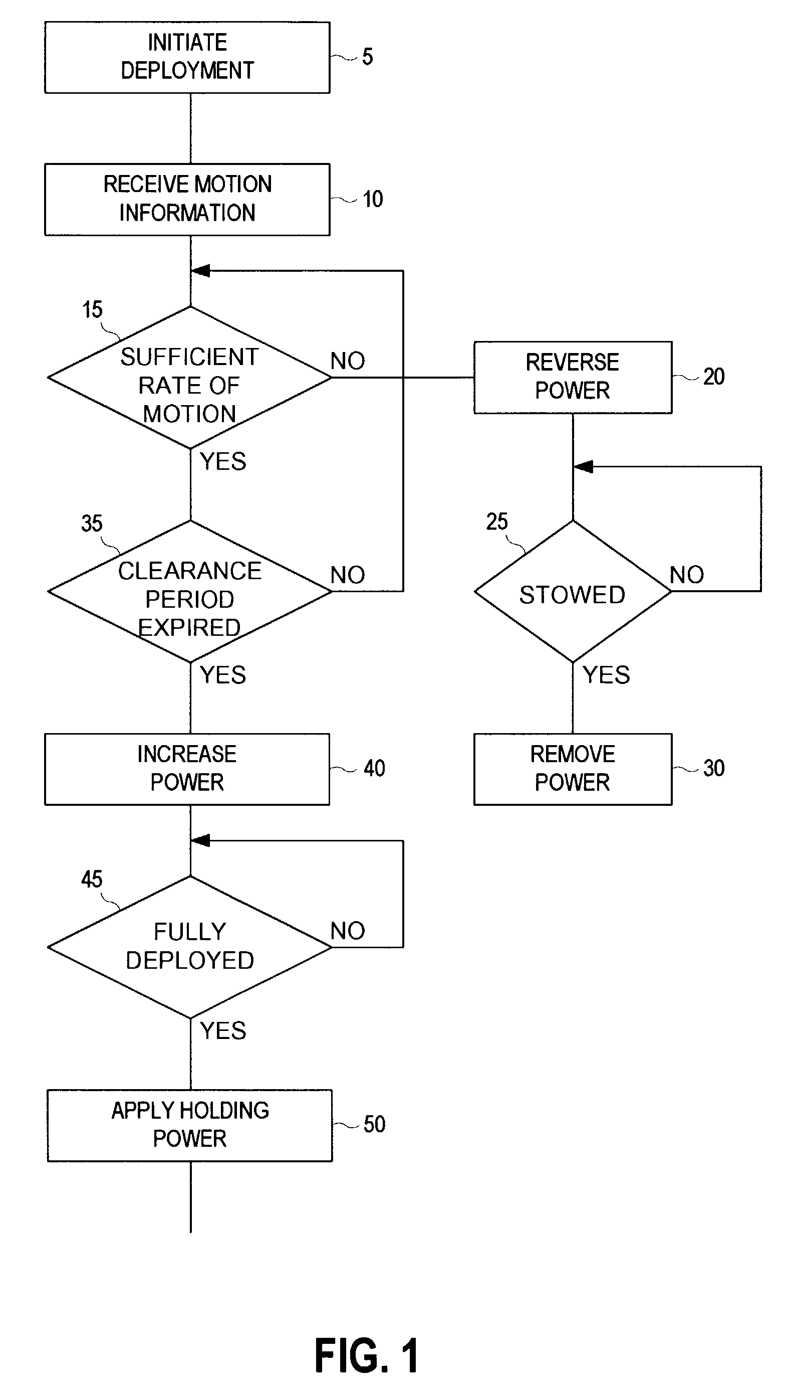
[0030]FIG. 1 is a flow diagram that depicts one illustrative process for deploying a deployable user interface from it's housing according to the present invention. The present method may be applicable in the case where an actuator is used to cause a deployable member to travel from a stowed position to a deployed position. Generally, deployment may begin (step 5) and motion infor...


PUM


Abstract

User interface devices, such as displays and keyboards, are automatically deployed using pulse-width-modulated controlled force in a first safety period. Once safe, force and speed are increased to full deployment. At full deployment, electrical braking dissipates mechanical energy and power is throttled down to hold device against deployment stop.

Description

FIELD OF THE INVENTION[0001]This invention relates generally to deployable user interface devices.BACKGROUND OF THE INVENTION[0002]The notion of providing retractable devices is not new. For many years, a wide variety of industries have used retractable devices such as keyboards and displays. These are just two examples of user interface devices that may be used in a deployed position and then retracted when they are not needed or otherwise intrude into a cluttered space.[0003]The aircraft industry has long used retractable user interface devices because of the limited operational space that is available either in the cockpit or in the passenger compartment of an aircraft. It is not uncommon to discover retractable keyboards that are used to control equipment disposed in the flight deck. Once the keyboard is not needed, it can be stowed so that it does not continue to clutter the operating space. This helps to promote the operational safety of the aircraft. Although not as common, r...

Claims


Application Information

Patent Timeline
Patent Type & Authority Patents(United States)
IPC IPC(8): G06F17/10
CPCB60R11/02B60R11/0235B60R2011/0028B60R2011/0082B60R2011/0085
Inventor BROBERG, DAVID W.BREGMAN, BURT
Owner BURRANA IP & ASSETS LLC
Why Eureka
Try Eureka