
System and method for pre-tensioning backing material

a backing material and pretensioning technology, applied in the field of prestretching and pretensioning backing materials, can solve the problems of reducing the drag or tension applied to the backing material, and the patterned elements formed along the side edges of carpets cannot be properly matched together, so as to reduce the amount of drag or tension placed on the backing material, the effect of varying the amount of tension or drag

Active Publication Date: 2007-05-15
CARD MONROE
View PDF41 Cites 56 Cited by
  • Summary
  • Abstract
  • Description
  • Claims
  • Application Information

AI Technical Summary

Benefits of technology

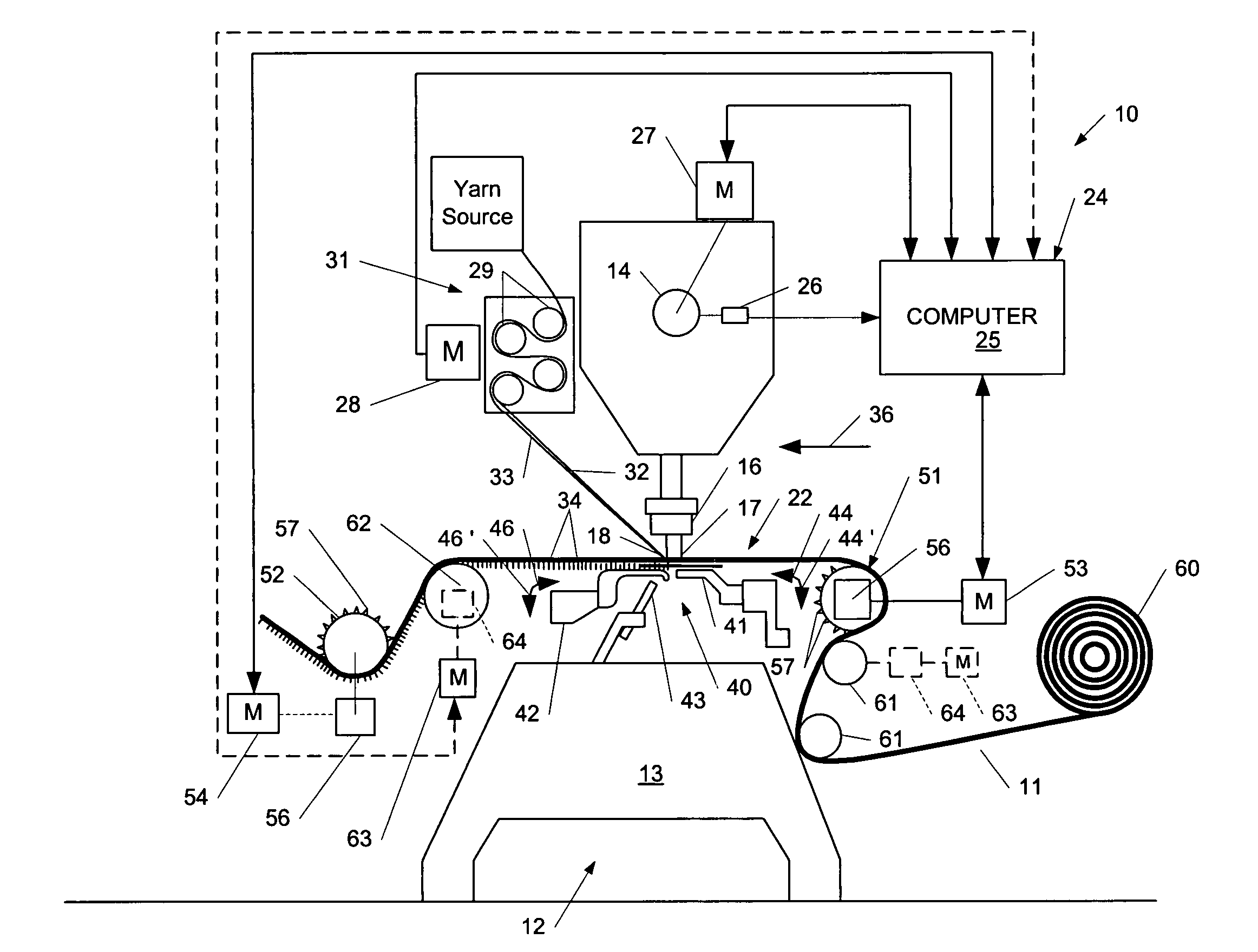
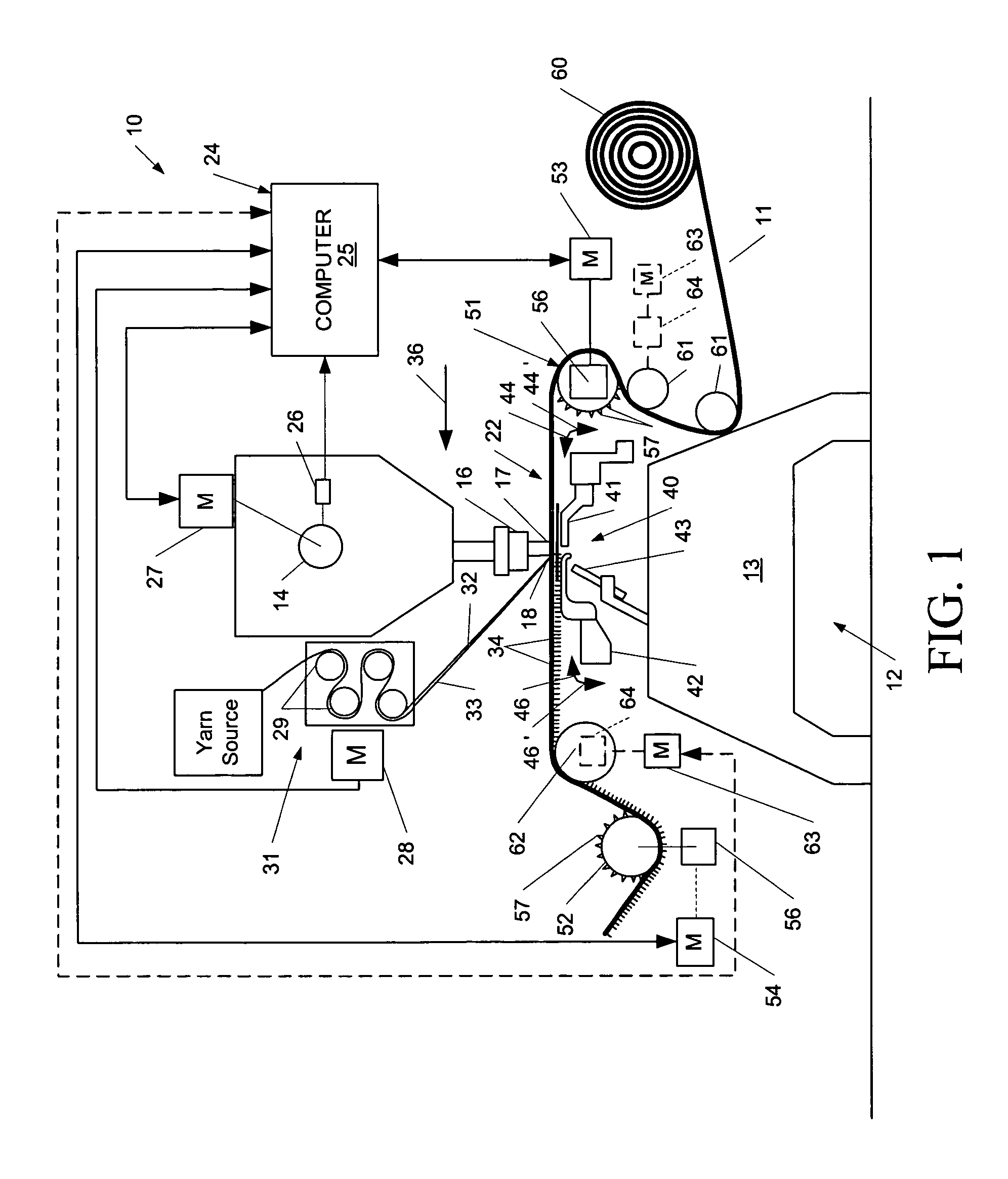
[0009]The operative functions of the tufting machine, including the yarn feed mechanism and control of the backing feed rolls, generally will be controlled by a tufting machine control system. The control system generally will include a processor or computer and can include a user interface for programming the tufting machine, or alternatively, can be connected to a computer network for receiving design or pattern information and instructions. The control system will monitor the operation of the backing feed or spike roll motors and will generate or determine a monitored or measured operating value, such as, for example, power / torque output, position, or speed of the motor shafts. The monitored operating value(s) will be compared to at least one programmed control value or, alternatively, can be compared to a similarly monitored comparison control value such as the power / torque output, position or speed of the motor shaft of the other backing feed or spike roll motor. If the monitored value falls outside a desired or programmed range, indicating too much or too little tension being applied to the portion of the backing material entering and passing through the tufting zone, the control system can adjust the operation of at least one of the backing feed or spike roll motors to compensate for any differences between the monitored and programmed or desired control values to accordingly adjust the amount of tension being applied to the backing material. This is designed to ensure substantially consistent stretching of the backing material so that a significant amount of the “necking in” of the backing material occurs prior to the backing material entering and passing through the tufting zone, so that any necking in of the backing material in the tufting zone is minimized to avoid problems with misalignment of the edges of the tufted article / carpet.
[0010]As a further alternative, an additional, third spike roll can be used in the system and method of pre-stretching or controlling the tensioning of the backing material according to the present invention. The third spike roll generally will be positioned adjacent the front or first spike / backing feed roll and can be monitored so as to determine a further monitored operating value, such as the position or speed of its motor shaft, a power / torque output value, or other measurement value. This monitored value can be compared with a monitored control value from one or both of the other spike roll or backing feed motors to determine whether each of the motor shafts are out of phase with each other. If the motor shafts are out of phase, i.e., indicating that the front spike roll is not following the rear spike roll and thus creating a variance in the amount of tension or drag being placed on the backing material, the speed of the monitored spike / backing feed roll can be generally varied. In addition, the third or additional spike roll can be operated at a relatively constant rate to assist in feeding the backing material or to apply a drag or tension, or can be run at a varied rate, either faster or slower, to help decrease or increase the amount of drag being placed on the backing material.

Problems solved by technology

This necking in of the backing material can cause side matching problems in finished carpets, especially patterned carpets, such that the patterned elements formed along the side edges of carpets cannot be properly matched together.
However, a problem still exists with respect to maintaining tension on the backing material as it is fed through the tufting machine, especially as the amount, and thus the weight, of backing material remaining on the supply roll decreases, which can accordingly decrease the drag or tension applied to the backing material by the weight of the supply roll itself and vary the load on the front spike roll.

Method used


Image

  • System and method for pre-tensioning backing material
  • System and method for pre-tensioning backing material
  • System and method for pre-tensioning backing material

Examples


Embodiment Construction

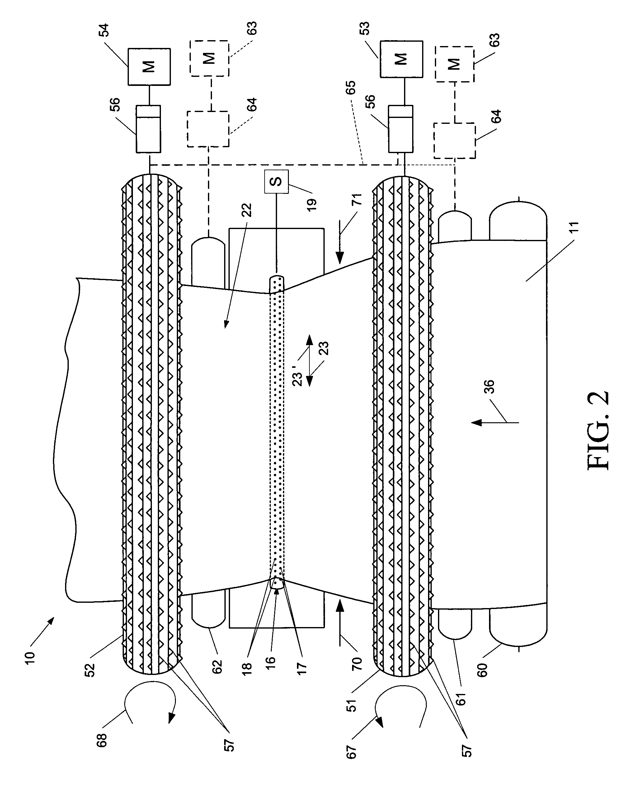
[0016]The present invention generally relates to a system 10 and method for pre-stretching and / or applying and controlling pre-stretching or tensioning of a backing material 11 being fed through the tufting zone of a tufting machine 12 for forming tufted articles such as carpets, rugs, etc. As shown in FIG. 1, the system 10 of the present invention for controlling the pre-tensioning and pre-stretching of the backing material fed to a tufting machine, generally will be mounted on a tufting machine 12 having a frame 13 and a main shaft 14 that drives one or more reciprocating needle bars 16. As shown in FIGS. 1–3, the needle bar 16 can be a single needle bar, including one or more rows of staggered needles 17 and 18 aligned in spaced series along the length of the needle bar in parallel rows staggered or separated from each other by a prescribed stagger distance. It will, however, be understood that while a single staggered needle bar 16 is shown in the drawings, it will also be possi...


PUM


Abstract

A tufting machine control system for controlling the tension applied to a backing material as it enters the tufting zone of the tufting machine, including a pair of driven backing feed rolls for feeding the backing material. The drive motors for the backing feed rolls are monitored by the control system and are adjusted to control the amount of tension applied to the backing material as it enters the tufting zone of the tufting machine.

Description

CROSS REFERENCE TO RELATED APPLICATIONS[0001]The present patent application is a formalization of previously filed, co-pending U.S. provisional patent application Ser. Nos. 60 / 611,881, filed Sep. 21, 2004, by the inventor named in the present application. This patent application claims the benefit of the filing date of the cited provisional patent application according to the statutes and rules governing provisional patent applications, particularly USC § 119(e)(1) and 37 CFR § 1.78(a)(4) and (a)(5). The specification and drawings of the provisional patent application are specifically incorporated herein by reference.FIELD OF THE INVENTION[0002]The present invention generally relates to a system and method for forming tufted articles, such as carpets, and in particular to a system and method for pre-stretching and pre-tensioning backing material being fed to the tufting zone of a tufting machine.BACKGROUND OF THE INVENTION[0003]Conventional tufting machines for forming tufted articl...

Claims


Application Information

Patent Timeline
Patent Type & Authority Patents(United States)
IPC IPC(8): D05C15/04
CPCD05C15/14
Inventor CHRISTMAN, JR., WILLIAM M.
Owner CARD MONROE
Learn More