Shaft drive unit, in particular an electrical drive unit for driving a wheel shaft with a transverse shaft structure

a technology of transverse shaft and drive unit, which is applied in the direction of electric propulsion mounting, electric devices, battery/cell propulsion, etc., can solve the problems of increasing the frequency-dependent effects of electrical, magnetic or electromagnetic fields on the environment, increasing the cost of line and cable routing, and reducing the reliability of the overall system. , to achieve the effect of optimal utilization of physical spa

Inactive Publication Date: 2007-05-15
VOITH TURBO GMBH & CO KG
View PDF17 Cites 20 Cited by
  • Summary
  • Abstract
  • Description
  • Claims
  • Application Information

AI Technical Summary

Benefits of technology

[0007]The invention is thus based on the object of further developing an embodiment of a shaft drive unit, in particular of an electrical drive unit, for driving wheel shafts of a vehicle in such a manner as to achieve optimum utilization of physical space by the components which can be associated with the electrical drive machine, while at the same time ensuring freedom from disturbance with regard to the other components required for the method of operation of the vehicle. In this case, these additional componen...

Problems solved by technology

Owing to the physical separation, the line and cable routing required for this purpose is generally also very expensive and complicated.
Furthermore, long cable runs also mean an increase in the frequency-dependent effects of electrical, magnetic or electromagnetic fields on the environment, in particular on living beings and technical systems.
A further major disadvantage of these embodiments is that the reliability of the overall system decreases as the ...

Method used


Image

  • Shaft drive unit, in particular an electrical drive unit for driving a wheel shaft with a transverse shaft structure
  • Shaft drive unit, in particular an electrical drive unit for driving a wheel shaft with a transverse shaft structure
  • Shaft drive unit, in particular an electrical drive unit for driving a wheel shaft with a transverse shaft structure

Examples


Embodiment Construction

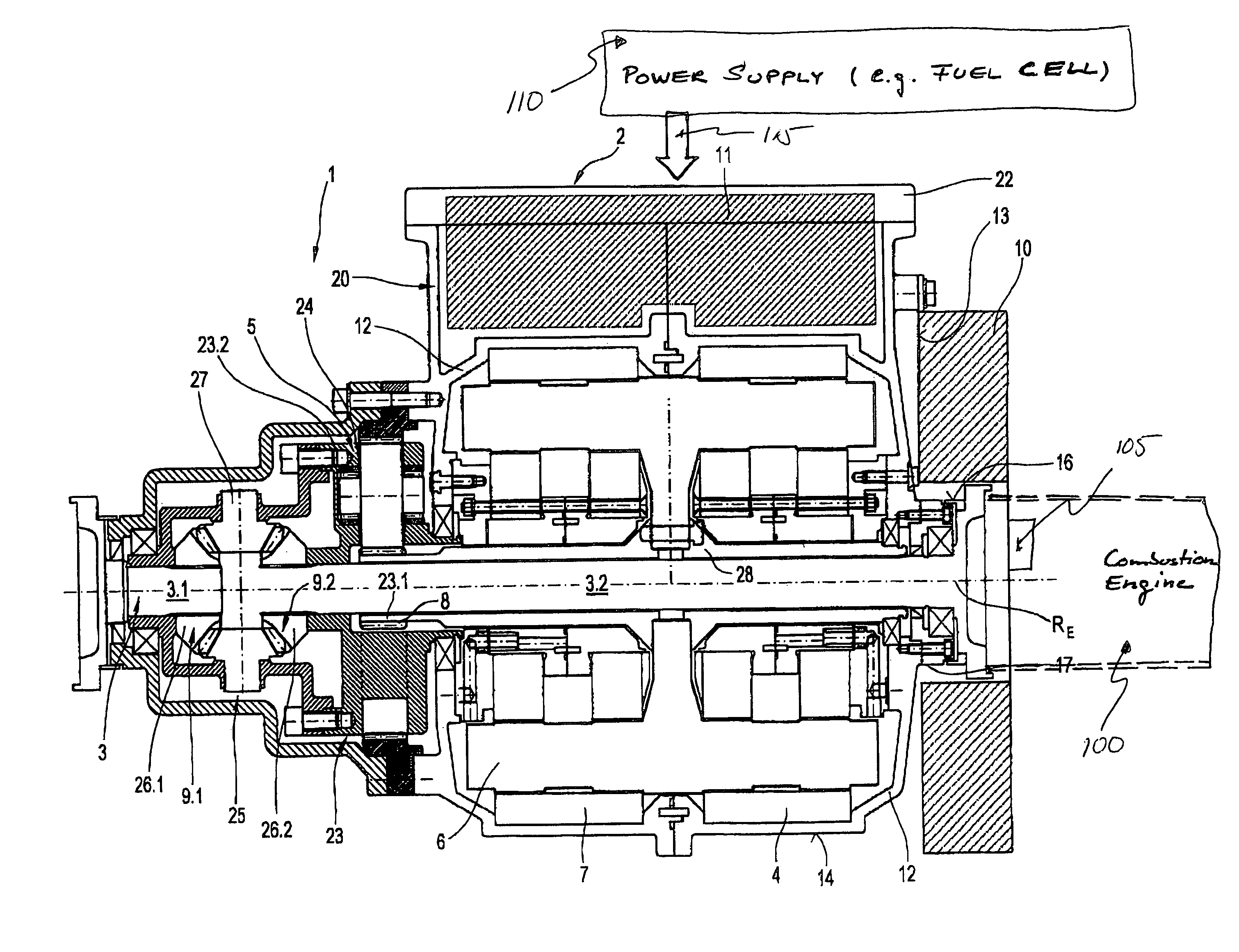
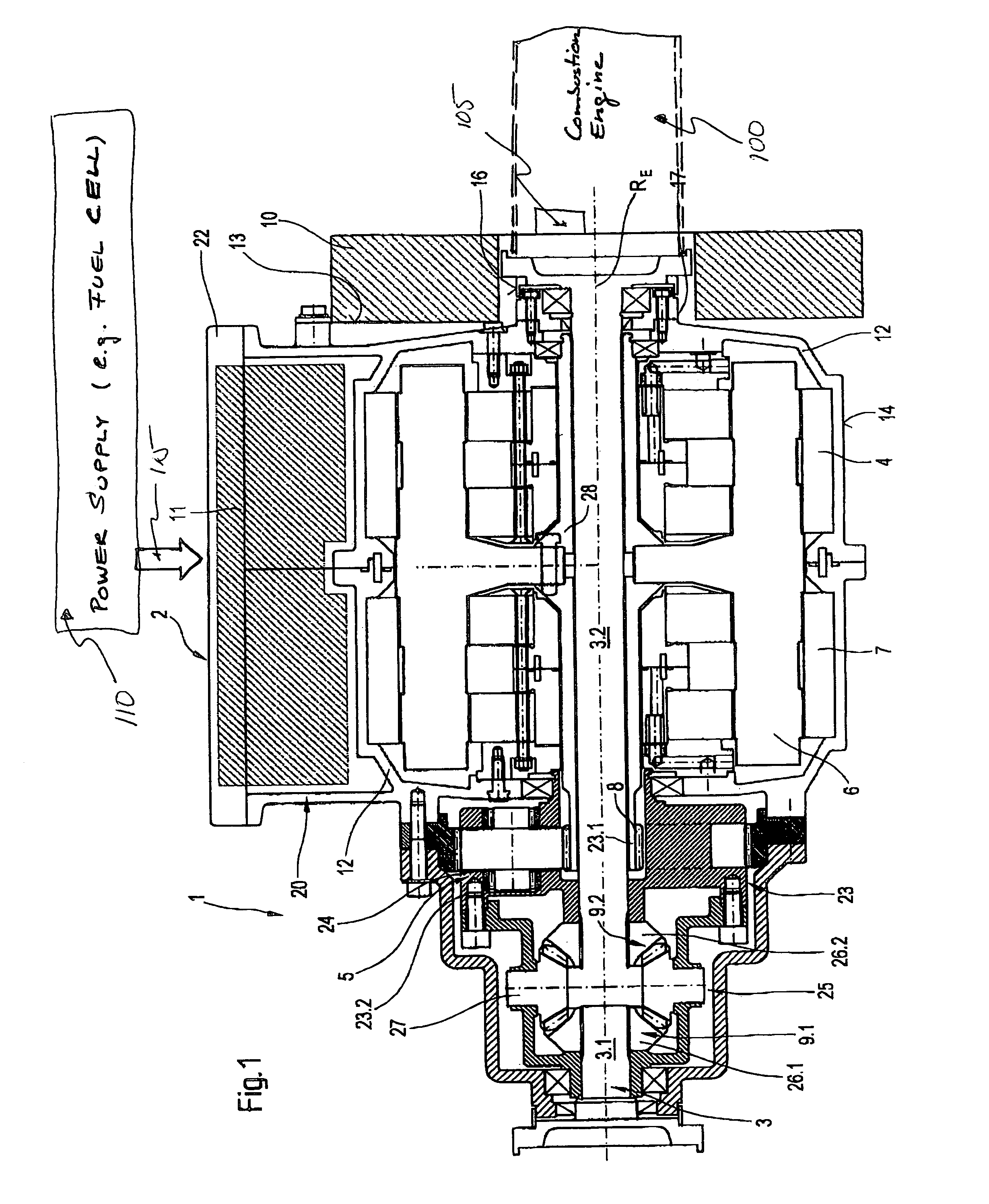
[0039]FIG. 1 uses an axial section to show the basic design of a shaft drive unit 1 designed according to the invention, in particular in the form of an electrical drive unit 2 for driving a wheel shaft 3 with a transverse shaft structure. The shaft drive unit 1 comprises at least one electrical machine 4, which acts as a drive motor in the traction mode, in particular an electric motor and a transmission unit 5 coupled to it. The transmission unit 5 is in this case arranged between the electrical machine 4 and the wheel shaft 3 which is to be driven. The expression wheel shaft is in this case chosen with respect to the wheels since the wheel shaft can be coupled in a rotationally fixed manner to the wheels, that is to say there is no relative movement between the wheel and the shaft. However, with respect to its operation, this acts as an input drive shaft. The electrical machine 4 has at least one rotor 6 and one stator 7, with the rotor 6 being connected in a rotationally fixed m...


PUM


Abstract

The invention relates to a shaft drive unit, in particular an electrical drive unit for driving a wheel shaft in vehicles; having an electrical machine comprising a rotor and a stator; having a transmission unit, comprising at least one input connected in a rotationally fixed manner to the rotor of the electrical machine, and at least one output connected in a rotationally fixed manner to the wheel shaft. The electrical machine, the input and the output of the transmission unit and the wheel shaft are arranged coaxially with respect to one another. The electrical machine has at least one associated converter unit and one associated braking resistor unit. The converter unit forms a physical unit with the electrical machine. The braking resistor unit is arranged in the immediate physical vicinity of the electrical machine and around the circumference of the input or output drive shaft of the electrical machine or of the wheel shaft.

Description

[0001]The invention relates to a shaft drive unit, in particular an electrical drive unit for driving a wheel shaft with a transverse shaft structure.BACKGROUND INFORMATION[0002]A large number of embodiments are known for the design configuration and construction of electrical drives for vehicles, in particular hybrid drives for vehicles. Embodiments for driving a front wheel shaft of a vehicle are in this case preferably designed using a transverse shaft structure. The shaft drive unit in this case comprises an electrical drive machine which can be operated as an electric motor in the traction mode and is connected to the wheel shaft via a transmission unit. The power for operating the electrical drive machine is provided via a power supply system which, depending on the choice of energy source, may have various configurations. Referring to FIG. 1, there is seen a power system in the form of an internal combustion engine 100 mechanically and electrically coupled to an electrical ma...

Claims


Application Information

Patent Timeline
IPC IPC(8): B60K6/02B60K1/00B60K6/26B60K6/32B60K6/46B60K17/04B60K17/16H02K7/106H02K7/116H02K11/00H02K11/04
CPCB60K1/00B60K6/32B60K6/46H02K7/106H02K7/116H02K11/048B60L3/003B60L7/06B60L11/1803B60K6/26Y02T10/641B60K17/046B60K17/165Y02T10/6217Y02T90/34B60L2240/36Y02T10/7005H02K11/0094B60L50/51Y02T10/62Y02T10/64Y02T10/70Y02T90/40H02K11/05
Inventor ANGERER, WOLFRAMMUHLBERGER, UWE
Owner VOITH TURBO GMBH & CO KG
Why Eureka
Try Eureka