Alternative method for sealing all-metal vacuum joints

Active Publication Date: 2007-05-15
KIMBALL PHYSICS
View PDF7 Cites 5 Cited by
  • Summary
  • Abstract
  • Description
  • Claims
  • Application Information

AI Technical Summary

Benefits of technology

[0010]Consistent with the present invention, it is possible to insert an additional component or components between two flanges, using only minimal space. The decrease in required space has the advantage of increasing the conductance of the vacuum system. Also, since the present invention does not require modifications to the inserted component or components, industry standard parts may be used in conjunction with the present invention. This last feature is particularly useful in mounting industry standard valves, as opposed to specially modified or specially manufactured valves. Furthermore, because all of the su

Problems solved by technology

The expense of a vacuum system lies in the cost of components, the required pump types and speeds, and the number and type of extra adapters needed to attach components to a system.
The prior art flanges do not adequately optimize some of these requirements, in some cases.
If at least one of the flange pairs is not rotatable, then the possible mounting configurat

Method used


Image

  • Alternative method for sealing all-metal vacuum joints
  • Alternative method for sealing all-metal vacuum joints
  • Alternative method for sealing all-metal vacuum joints

Examples


Example

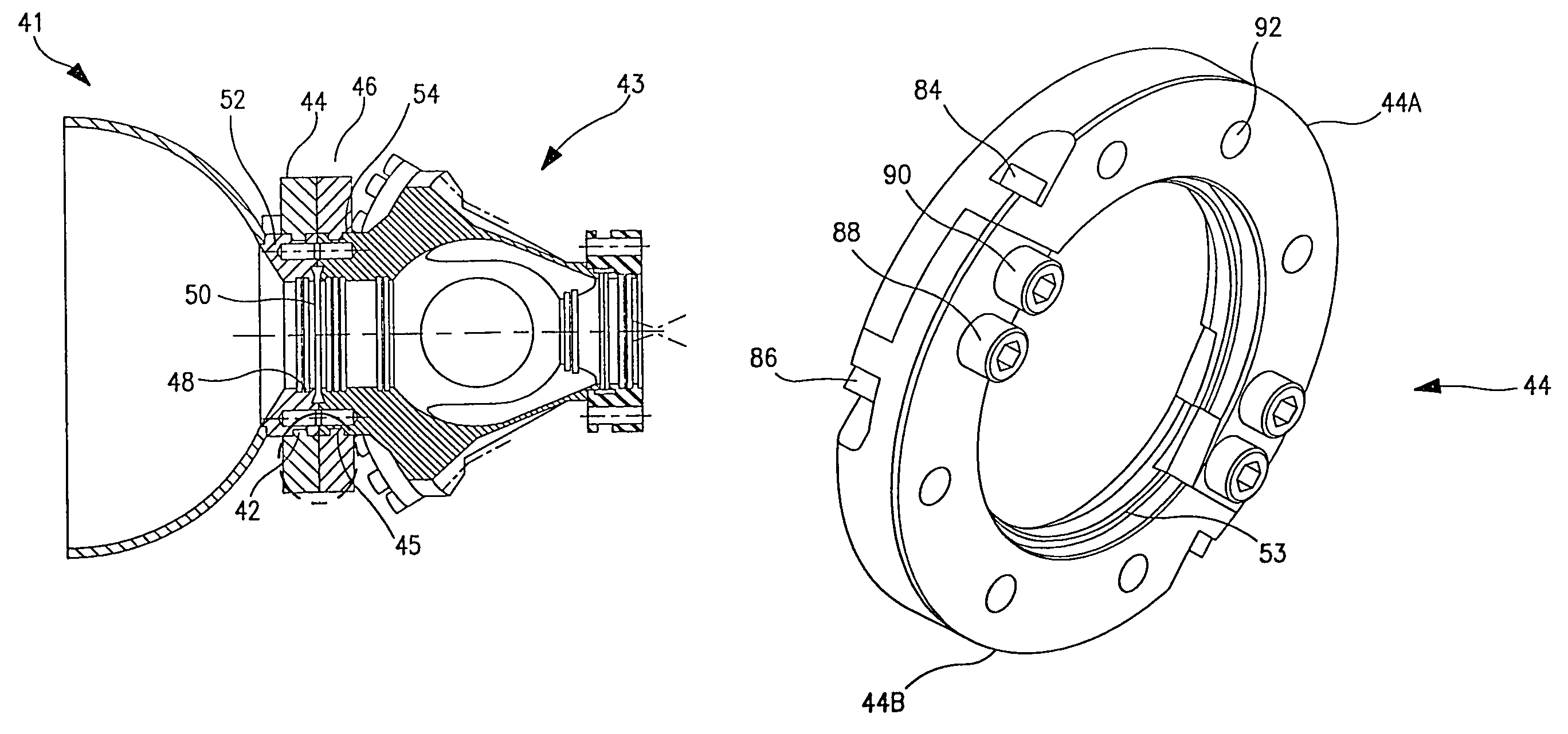
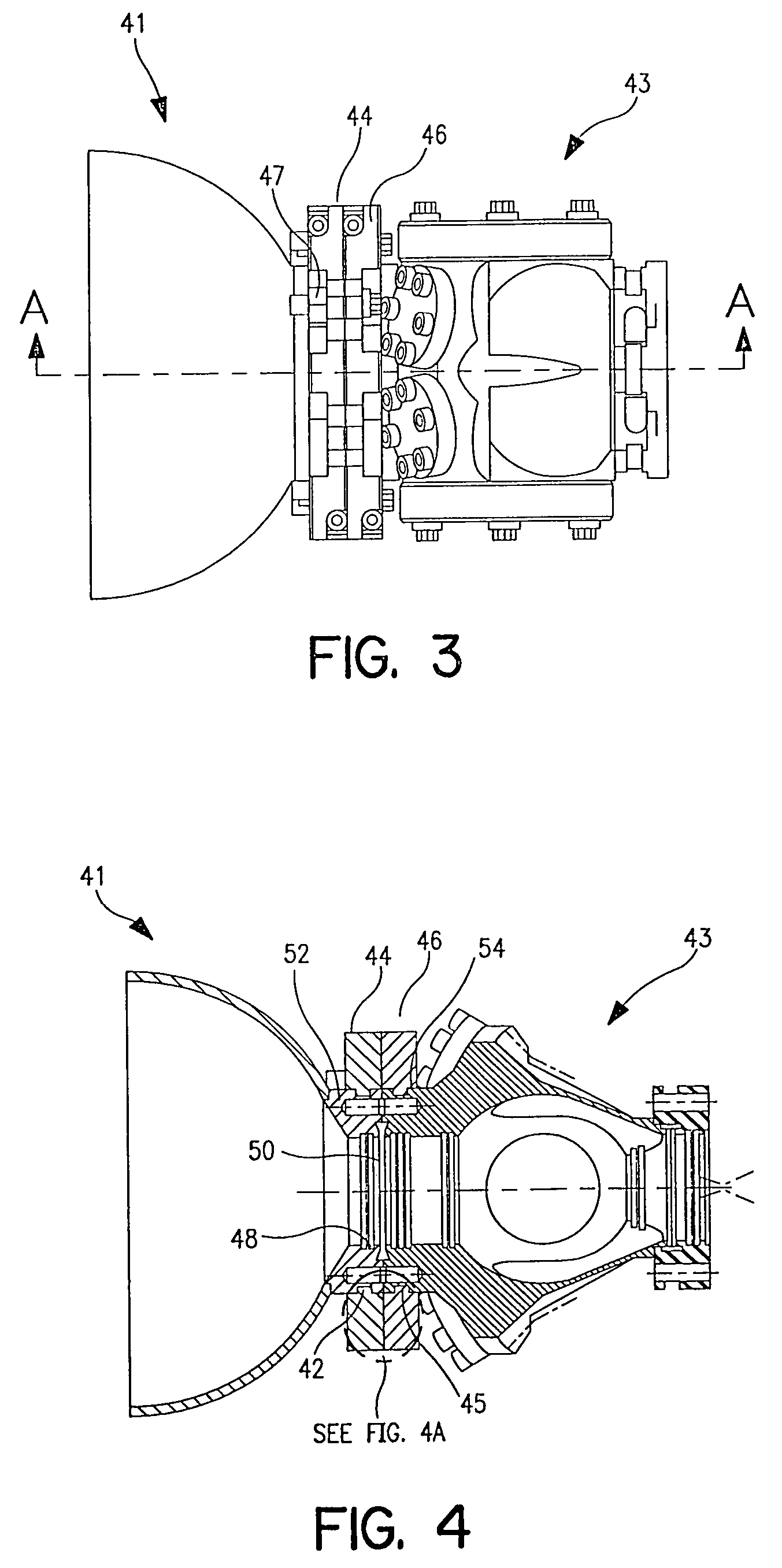
[0020]Referring to first to FIGS. 3 and 4, an exemplary embodiment of the clamping system consistent with the present invention. FIG. 3 shows a first and a second vacuum system component 41 and 43 each having a corresponding clamp member 44 and 46 respectively attached thereto. The two clamp members 44 and 46 are further joined or secured to one another using auxiliary bolts, one of which is indicated at 47.

[0021]Turning to FIG. 4, a sectional view of the assembly shown in FIG. 3 is illustrated. The individual clamp members 44 and 46 are each attached to respective flanges 52 and 54 of vacuum system components 41 and 43. Each of the flanges 52 and 54 comprise a groove 42 and 45 formed in the outer edge of each flange 52 and 54. The attachment of the clamp members 44 and 46 may advantageously be achieved by means of beads 53 and 55 projecting from the clamp members 44 and 46. It should be appreciated that the beads 53 and 55 may be either continuous or discontinuous, and may also be ...


PUM

PropertyMeasurementUnit
Forceaaaaaaaaaa
Vacuumaaaaaaaaaa

Abstract

A clamping system for high or ultra-high vacuum system components including a clamping member surrounding a flange of the vacuum system component. A bead along the inside diameter of the clamping member engages a groove in the peripheral surface of the flange. When a clamping force is applied to the clamping member, as by a bolt, the force is transmitted to the flange providing sufficient clamping force to form a vacuum seal.

Description

[0001]This Application also is a divisional of U.S. application Ser. No. 10 / 014,163, filed Oct. 26, 2001 now U.S. Pat. No. 6,678,937.CROSS-REFERENCE TO RELATED APPLICATIONS[0002]This application claims the benefit of U.S. provisional application Ser. No. 60 / 243,527 filed on Oct. 26, 2000, the teachings of which are incorporated herein by reference.FIELD OF INVENTION[0003]This invention relates to clamping systems for high and ultra-high vacuum systems.BACKGROUND OF THE INVENTION[0004]Vacuum systems find wide applications in research, education, product development, and production. Typical systems are comprised of independent and interchangeable components. Components include testing chambers, pumps, gauges, valves, specimen holders, electron sources, ion sources, photon sources, molecular beam sources, detectors of various types, etc.[0005]Processes or experiments that require high or ultra-high vacuum (UHV) currently employ all metal vacuum joints. A typical all-metal joint, such a...

Claims


Application Information

Patent Timeline
IPC IPC(8): F16L23/00F16L23/024
CPCF16L23/024Y10T29/49908Y10T29/49913
Inventor CRAWFORD, CHARLES K.
Owner KIMBALL PHYSICS
Why Eureka
Try Eureka