
Rotor blade with a stick damper

a technology of rotating blades and dampers, applied in the field of rotating blades, to achieve the effects of reducing stress, enhancing cooling, and reducing cross-sectional area

Active Publication Date: 2007-05-15
RTX CORP
View PDF8 Cites 27 Cited by
  • Summary
  • Abstract
  • Description
  • Claims
  • Application Information

AI Technical Summary

Benefits of technology

"The present invention provides a rotor blade damper that allows for a desirable narrow thickness of the blade at the tip. The damper is tapered, with a smaller cross-sectional area tip, which reduces stress and allows for greater centrifugal loading between the damper and the blade. The tapered body of the damper also facilitates cooling and reduces the likelihood of blockage. The cooling channels are strategically placed to minimize stress concentration factors and provide efficient cooling. Overall, the present invention provides improved durability and performance of the rotor blade."

Problems solved by technology

The thickness of many prior art dampers prohibits the use of a damper within a rotor blade having a narrow tip region.

Method used


Image

  • Rotor blade with a stick damper
  • Rotor blade with a stick damper
  • Rotor blade with a stick damper

Examples


Embodiment Construction

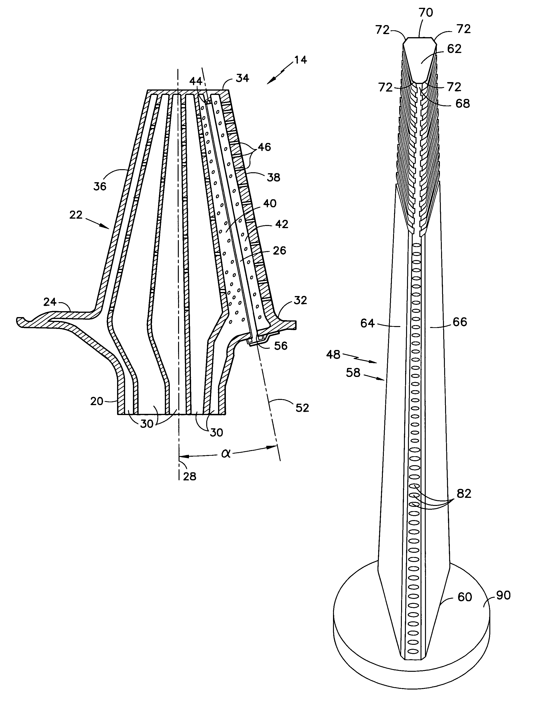
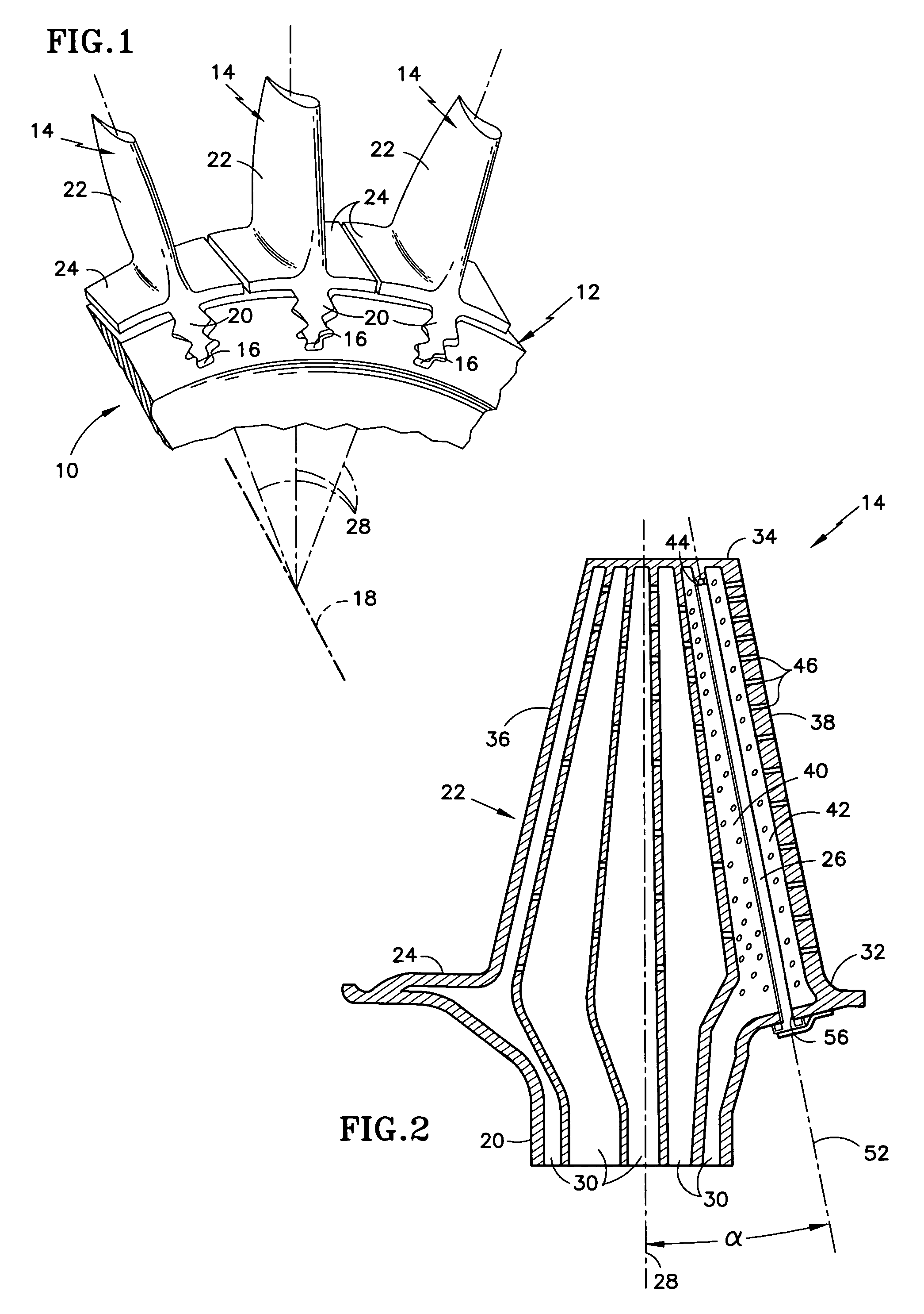
[0028]Referring to FIG. 1, a rotor blade assembly 10 for a gas turbine engine is provided having a disk 12 and a plurality of rotor blades 14. The disk 12 includes a plurality of recesses 16 circumferentially disposed around the disk 12 and a rotational centerline 18 about which the disk 12 may rotate. Each blade 14 includes a root 20, an airfoil 22, a platform 24, and a damper 26 (see FIG. 2). Each blade 14 also includes a radial centerline 28 passing through the blade 14, perpendicular to the rotational centerline 18 of the disk 12. The root 20 includes a geometry (e.g., a fir tree configuration) that mates with that of one of the recesses 16 within the disk 12. The root 20 further includes conduits 30 through which cooling air may enter the root 20 and pass through into the airfoil 22.

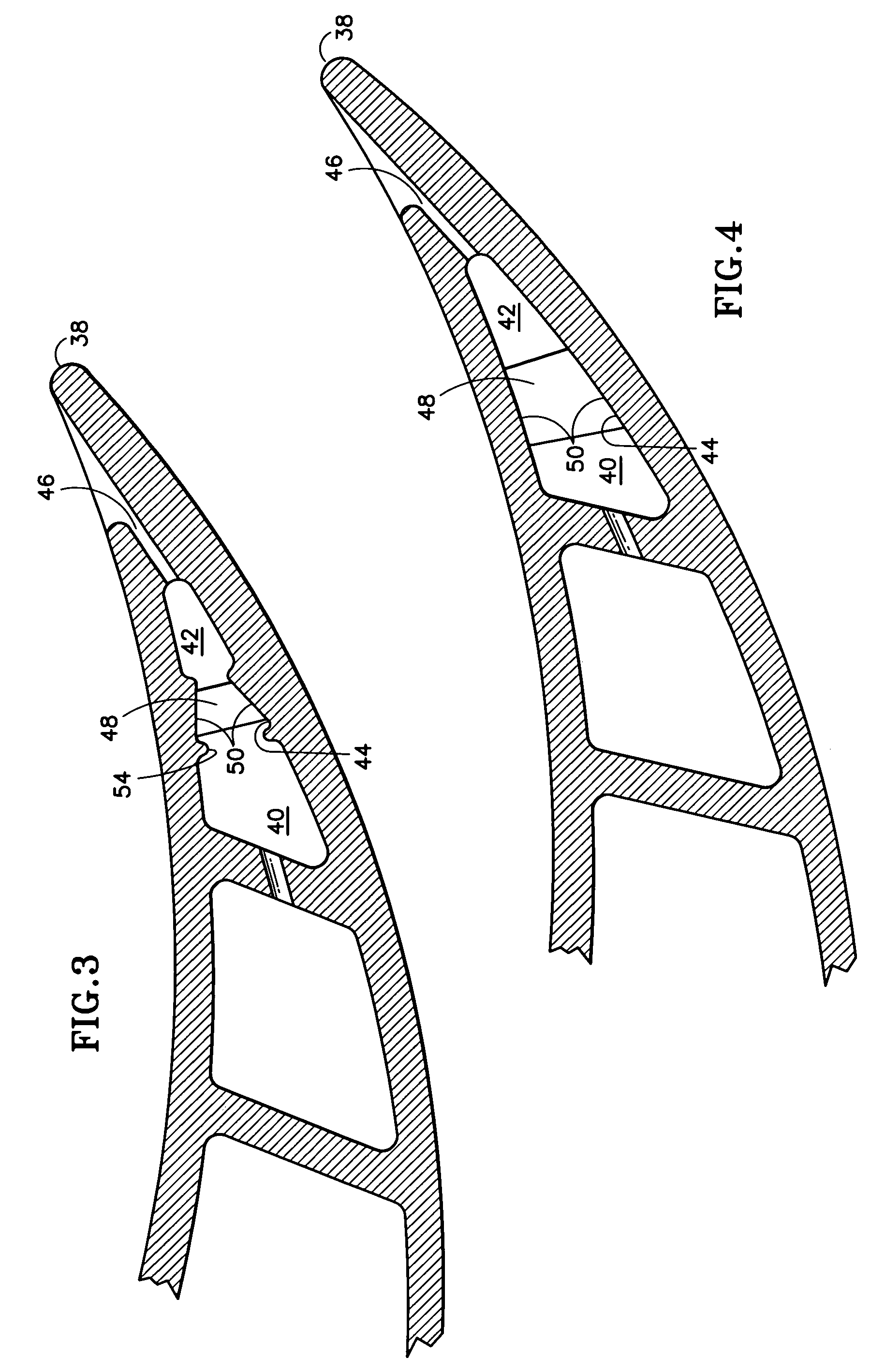
[0029]Referring to FIGS. 2 and 3, the airfoil 22 includes a base 32, a tip 34, a leading edge 36, a trailing edge 38, a first cavity 40, a second cavity 42, and a passage 44 between the first and se...


PUM


Abstract

A rotor blade damper is provided that includes a body having a base, a tip, a first contact surface, a second contact surface, a trailing edge surface, and a leading edge surface. The trailing edge and the leading edge surfaces extend between the contact surfaces. The first contact surface, second contact surface, trailing edge surface, and leading edge surface all extend lengthwise between the base and the tip. The body includes at least one cooling aperture disposed adjacent the base, that has a diameter that is approximately equal to or greater than the width of the trailing edge surface adjacent the tip. The body tapers between the base and the tip such that a first widthwise cross-sectional area adjacent the base is greater than a second widthwise cross-sectional area adjacent the tip.

Description

[0001]The invention was made under a U.S. Government contract and the Government has rights herein.BACKGROUND OF THE INVENTION[0002]1. Technical Field[0003]This invention applies to rotor blades in general, and to apparatus for damping vibration within a rotor blade in particular.[0004]2. Background Information[0005]Turbine and compressor sections within an axial flow turbine engine generally include a rotor assembly comprising a rotating disc and a plurality of rotor blades circumferentially disposed around the disk. Each rotor blade includes a root, an airfoil, and a platform positioned in the transition area between the root and the airfoil. The roots of the blades are received in complementary shaped recesses within the disk. The platforms of the blades extend laterally outward and collectively form a flow path for fluid passing through the rotor stage. The forward edge of each blade is generally referred to as the leading edge and the aft edge as the trailing edge. Forward is d...

Claims


Application Information

Patent Timeline
Patent Type & Authority Patents(United States)
IPC IPC(8): F01D5/26F01D5/16F01D5/18F16F15/12
CPCF01D5/16F05D2260/22141Y10S416/50F05D2260/96F01D5/12F01D5/18
Inventor PROPHETER, TRACY A.SURACE, RAYMOND C.
Owner RTX CORP
Learn More