Accommodating intraocular lens having peripherally actuated deflectable surface and method

a deflectable surface and peripheral actuator technology, applied in intraocular lenses, prostheses, medical science, etc., can solve the problems of preventing widespread commercialization of such devices, unable to accommodate, and typically already lost ability, and achieve the effect of varying the accommodation of the iol

Active Publication Date: 2007-05-15
ALCON INC
View PDF5 Cites 157 Cited by
  • Summary
  • Abstract
  • Description
  • Claims
  • Application Information

AI Technical Summary

Benefits of technology

[0020]It is a further object of this invention to provide methods and apparatus wherein a dynamic lens surface may be effectively manipulated by the ciliary muscular mechanisms within the eye.
[0022]It is a further object of this invention to provide methods and apparatus for applying muscular pressure, through one or more actuators, to obtain a mechanical advantage in altering the optical parameters of one or more surfaces of the IOL.
[0023]It is yet a further object of this invention to provide methods and apparatus that reduce the possibility of reflections within the IOL arising due to movement of mechanical actuators situated along or near the optical axis of the IOL.
[0025]In accordance with the principles of the invention, an IOL is provided having a dynamic lens surface that deflects in response to forces applied to one or more haptics. In a preferred embodiment, the deformable surface is anchored to a substrate near the optical axis of the IOL, and is deformed from an accommodated state to an unaccommodated state by deflection of the periphery of the deformable surface. In this manner, the IOL of the present invention reduces the possibility that light entering the IOL may be reflected due to movement of an actuator disposed at or near the optical axis of the IOL.

Problems solved by technology

Since the lens can no longer accommodate, however, the patient typically needs glasses for reading.
After placement, accommodation is no longer possible, although this ability is typically already lost for persons receiving an IOL.
Although previously known workers in the field of accommodating IOLs have made some progress, the relative complexity of the methods and apparatus developed to date have prevented widespread commercialization of such devices.
Previously known devices have proved too complex to be practical to construct or have achieved only limited success, due to the inability to provide accommodation of more than 1–2 diopters.

Method used


Image

  • Accommodating intraocular lens having peripherally actuated deflectable surface and method
  • Accommodating intraocular lens having peripherally actuated deflectable surface and method
  • Accommodating intraocular lens having peripherally actuated deflectable surface and method

Examples


Embodiment Construction

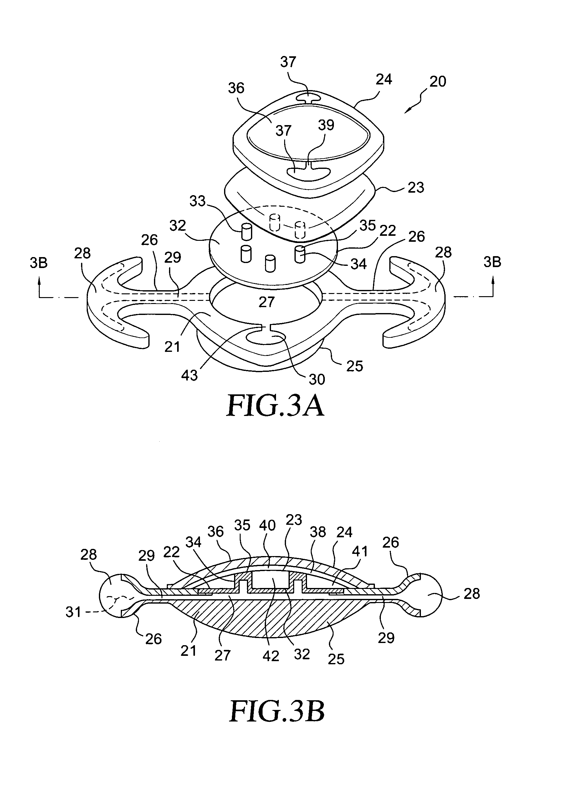
[0035]The present invention is directed to an in-situ accommodating intraocular lens system. In accordance with the principles of the present invention, methods and apparatus are provided wherein a lens has an optic element comprising a deformable surface and an actuator that selectively deflects the deformable surface to change an optical power of the lens. In accordance with the principles of the present invention, a central portion of the deformable surface is anchored to a substrate and the lens transitions between the accommodated and unaccommodated positions by deflection of a peripheral region of the deformable surface.

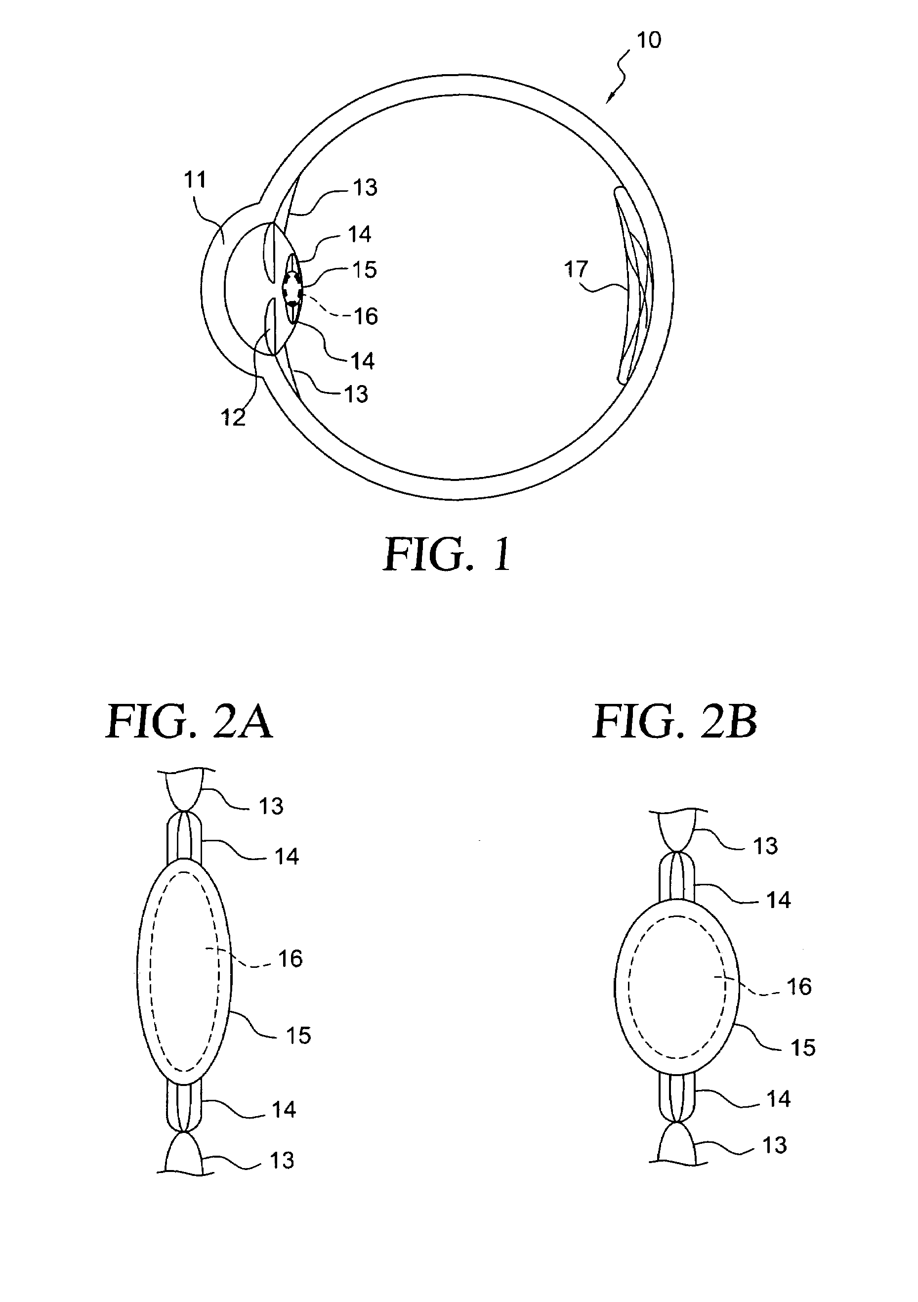
[0036]Referring to FIGS. 1 and 2, the structure and operation of a human eye are first described as context for the present invention. Eye 10 includes cornea 11 pupil 12, ciliary muscles 13, ligament fibers 14, capsule 15, lens 16 and retina 17. Natural lens 16 is composed of viscous, gelatinous transparent fibers, arranged in an “onion-like” layered structure,...


PUM


Abstract

An accommodating intraocular lens is provided in which a deflectable lens element is anchored to a substrate along its optical axis to define a fluid filled space. Fluid-filled haptics disposed in fluid communication with the space vary the fluid volume in the space responsive to forces applied by the ciliary muscles, thereby causing the periphery of the lens element to deflect relative to the substrate and changing the optical power of the intraocular lens.

Description

REFERENCE TO RELATED APPLICATIONS[0001]This application is a continuation-in-part of U.S. patent application Ser. No. 10 / 971,598, filed Oct. 22, 2004 now pending, which is a continuation-in-part of U.S. patent application Ser. No. 10 / 734,514, filed Dec. 12, 2003 now U.S. Pat. No. 7,122,053, which claims the benefit of priority from U.S. provisional application No. 60 / 433,046, filed Dec. 12, 2002.FIELD OF THE INVENTION[0002]The present invention relates to intraocular lenses (“IOLs”) having optical parameters that are changeable in-situ. More particularly, the invention has applications in IOLs for in-capsule implantation for cataract patients, wherein forces applied by the ciliary muscles in the eye induce movement of fluid media within the interior of the IOL, thereby altering an optical power of the lens to provide accommodation.BACKGROUND OF THE INVENTION[0003]Cataracts are a major cause of blindness in the world and the most prevalent ocular disease. Visual disability from catar...

Claims


Application Information

Patent Timeline
Patent Type & Authority Patents(United States)
IPC IPC(8): A61F2/16
CPCA61F2/1613A61F2/1635A61F2/1648A61F2250/0053A61F2002/1682
Inventor ESCH, VICTORSCHOLL, JOHNSMILEY, TERRYMYALL, PATRICKEVANS, BILLCHESKIN, BARRYWU, HENRY
Owner ALCON INC
Why Eureka
Try Eureka