Internal combustion engine having an improved oil cooling structure, and personal watercraft incorporating same

a technology of internal combustion engine and cooling structure, which is applied in the direction of machines/engines, marine propulsion, vessel construction, etc., can solve the problems of accelerated deterioration of lubricating oil, negative effect on oil life, and internal combustion engine supercooling, so as to prevent dilution, accelerate engine heating, and prevent supercooling

Inactive Publication Date: 2007-05-22
HONDA MOTOR CO LTD
View PDF13 Cites 6 Cited by
  • Summary
  • Abstract
  • Description
  • Claims
  • Application Information

AI Technical Summary

Benefits of technology

[0011]According to the first aspect of the invention, based on the temperature of the lubricating oil when it reaches the oil thermostat provided in the upstream oil path, the thermostat regulates the oil so that it bypasses the oil cooler when the temperature of the lubricating oil is below the predetermined temperature. The oil which bypasses the oil cooler is not cooled, whereby warm-up of the engine is accelerated. Thus, in cold water operation, supercooling is prevented. Moreover, even if fuel in a combustion chamber invades the crankcase and is mixed with the oil, evaporation is accelerated as the temperature of the oil rises, and the occurrence of dilution is prevented.

Problems solved by technology

However, in very cold water conditions, supercooling of the internal combustion engine may occur.
As a result, deterioration of the lubrication oil is accelerated, having a negative effect upon the life of oil.

Method used


Image

  • Internal combustion engine having an improved oil cooling structure, and personal watercraft incorporating same
  • Internal combustion engine having an improved oil cooling structure, and personal watercraft incorporating same
  • Internal combustion engine having an improved oil cooling structure, and personal watercraft incorporating same

Examples


Embodiment Construction

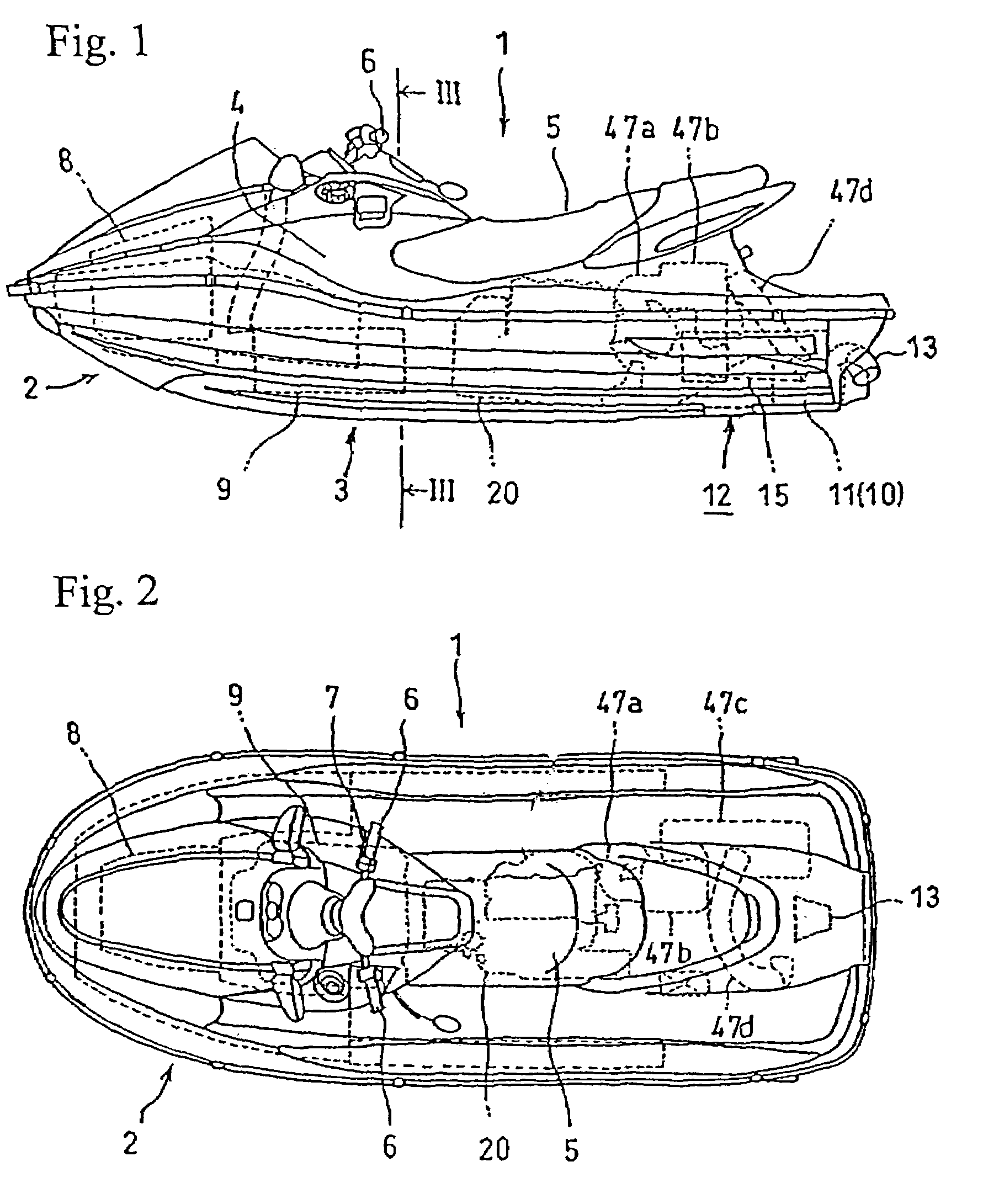
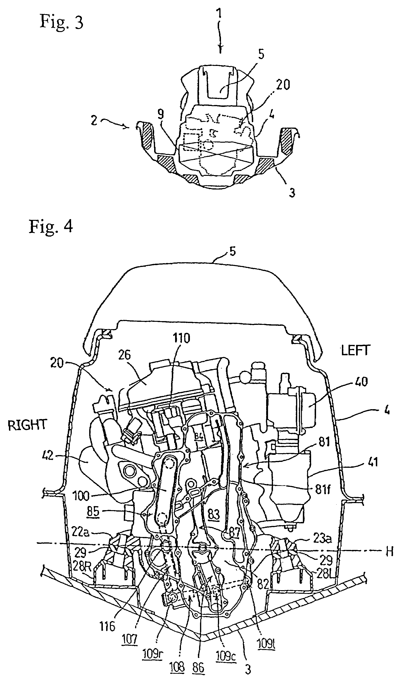
[0033]A selected illustrative embodiment of the invention will now be described in some detail, with reference to FIGS. 1 through 17. It should be understood that only structures considered necessary for clarifying the present invention are described herein. Other conventional structures, and those of ancillary and auxiliary components of the system, are assumed to be known and understood by those skilled in the art. Further, in the description provided herein, the right and left orientation is determined with reference forward advancing direction of the watercraft body.

[0034]A side plan view of a personal watercraft 1, according to the present invention, is illustrated in FIG. 1. The personal watercraft 1 has an internal combustion engine 20 mounted therein in accordance with a selected illustrative embodiment hereof. FIG. 2 illustrates a top plan view of the personal watercraft 1 of FIG. 1, and FIG. 3 illustrates a sectional view of the personal watercraft 1 of FIG. 1.

[0035]The pe...


PUM


Abstract

The use of an oil cooler in an internal combustion engine for a personal watercraft is controlled, whereby excessive cooling of the engine during warmup with cold water operation is avoided, and dilution of oil is substantially prevented. The internal combustion engine includes a bypass oil path connecting respective oil paths upstream and downstream of the oil cooler. The bypass oil path permits oil to be selectively detoured around the oil cooler. An oil thermostat is provided in the upstream oil path for selectively opening either a path to the oil cooler or the bypass oil path, and the oil thermostat is operable to switch the flow of oil therebetween. The oil thermostat opens the bypass oil path when the temperature of the oil is below a predetermined temperature, and directs oil to the oil cooler when the temperature of the oil is equal to or exceeds a predetermined temperature.

Description

CROSS-REFERENCE TO RELATED APPLICATIONS[0001]The present invention claims priority under 35 USC 119 based on Japanese patent application No. 2004-284547, filed on Sep. 29, 2004. The subject matter of this priority document is incorporated by reference herein.BACKGROUND OF THE INVENTION[0002]1. Field of the Invention[0003]This invention relates to an internal combustion engine, mounted on a personal watercraft which is designed for operation in water. More particularly, the invention relates to an internal combustion engine having an improved lubricating oil cooling structure.[0004]2. Description of the Background Art[0005]The personal watercraft, or small-sized planing boat, is constructed such that an internal combustion engine, for driving a jet propulsion pump, is mounted in a boat body and enclosed by a hull and a deck. A driver and up to two other crew members ride on the deck, so that an internal cabin space, constituted by the space between the hull and the deck, is narrow. T...

Claims


Application Information

Patent Timeline
Patent Type & Authority Patents(United States)
IPC IPC(8): F01M5/00B63H21/21
CPCB63H21/21F01M5/007B63H21/24
Inventor HOI, YOSUKEMATSUO, HISASHIIZUMI, MICHIOOKADA, KAZUNORI
Owner HONDA MOTOR CO LTD
Why Eureka
Try Eureka