Transformer

a transformer and transformer technology, applied in the field of transformers, can solve the problems of affecting the resonant circuit of the power supply system, the structure of the transformer is readily distorted, and the procedure of wrapping the tape , so as to increase the leakage inductance of the transformer, enhance the electric safety, and increase the distance

Active Publication Date: 2007-05-22
DELTA ELECTRONICS INC
View PDF4 Cites 18 Cited by
  • Summary
  • Abstract
  • Description
  • Claims
  • Application Information

AI Technical Summary

Benefits of technology

[0010]An object of the present invention is to provide a transformer, which employs a partition plate to separate the primary winding coil and the secondary winding coil, or disposes the first winding portion and the second winding portion in the receptacles at different sides of the main body, respectively, to increase the distance between the primary winding coil and the secondary winding coil so as to increase the leakage inductance of the transformer. Moreover, the leakage inductance of the transformer can be adjusted through the distance between the protrusion of the U-shaped magnetic core and the I-shaped magnetic core, so as to enhance the electric safety and solve the defects of the prior art.
[0011]Another object of the present invention is to provide a transformer whose leakage inductance can be adjusted through the magnetic core assembly, so that it does not need to redevelop a new model for the bobbin, so as to reduce the manufacturing cost, time and labor.

Problems solved by technology

Since the tape 24 is made of flexible material and fails to be firmly fixed, the structure of the transformer is readily distorted due to a long-term using period or serious vibration.
Under this circumstance, the magnitude of the leakage inductance is reduced or unstable, and the resonant circuit of the power supply system will be adversely affected.
Since these tapes are sticky and narrow in width, the procedures of wrapping the tape 24, the first side tape 25 and the second side tape 26 are labor-intensive and complicated.
In addition, if the wrapping result is unsatisfied, the electrical performance of the transformer is impaired.
The insulating tape also impairs heat dissipation of the transformer during operation.
With increasing development of electronic technologies, the electric conversion efficiency of a power converter to be used in an electronic product is gradually demanding.
Unfortunately, since the width d of the tape 24 is insufficient and the converted voltage is too high, the conduction between the primary winding coil and the secondary winding coil is possible.

Method used


Image

  • Transformer
  • Transformer
  • Transformer

Examples


Embodiment Construction

[0034]The present invention will now be described more specifically with reference to the following embodiments. It is to be noted that the following descriptions of preferred embodiments of this invention are presented herein for purpose of illustration and description only; it is not intended to be exhaustive or to be limited to the precise form disclosed.

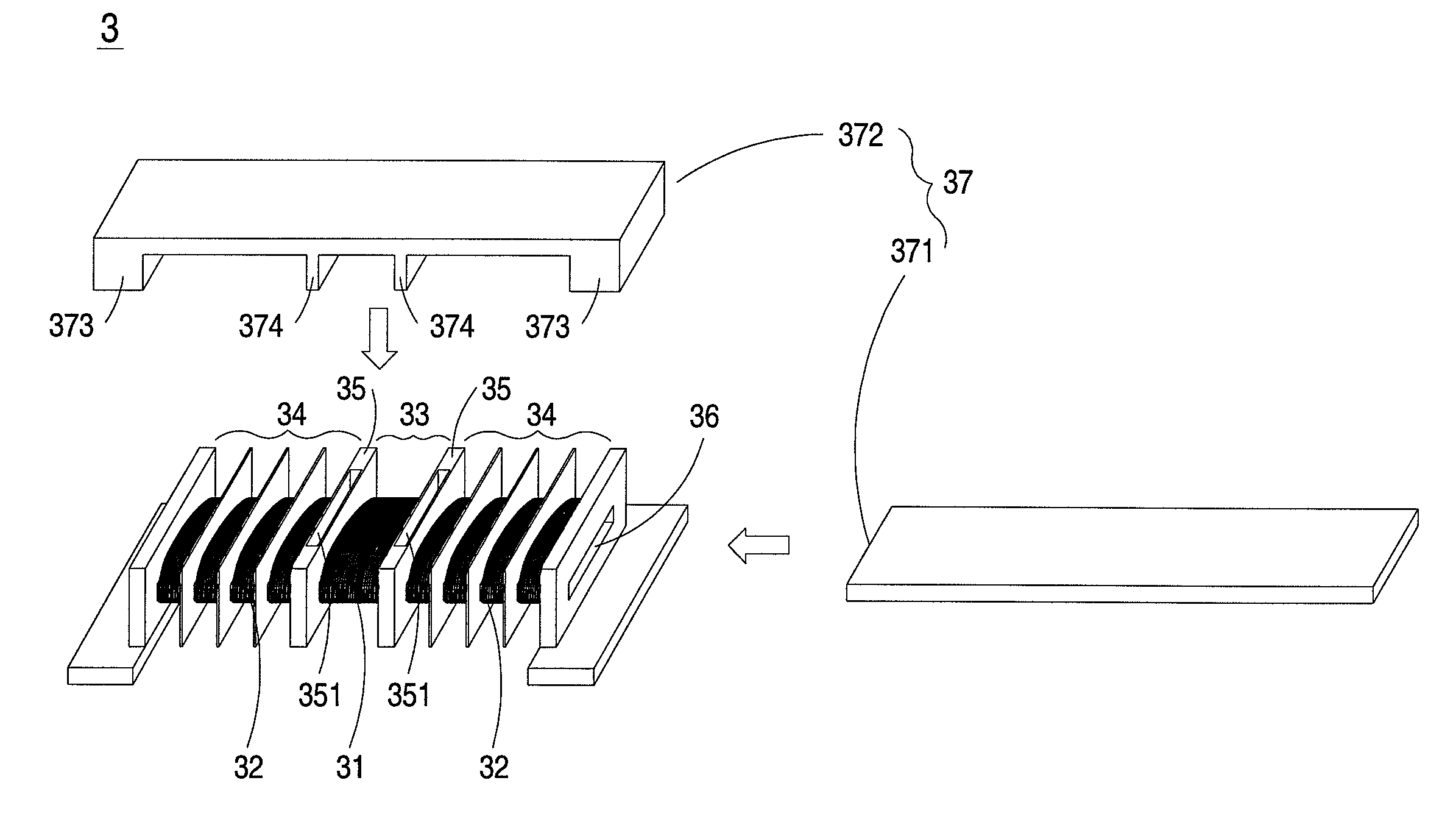
[0035]Please refer to FIG. 3(a), which is a schematic diagram showing the disassembled structure of the transformer according to the first preferred embodiment of the present invention. As shown in FIG. 3(a), the transformer 3 comprises a primary winding coil 31, plural secondary winding coils 32, a first winding portion 33, plural second winding portions 34, plural partition plates 35, a channel 36 and a magnetic core assembly 37. The first winding portion 33 is used for winding the primary winding coil 31 thereon, and the plural second winding portions 34 are used for winding the plural secondary winding coils 31 thereon and di...


PUM

PropertyMeasurementUnit
voltageaaaaaaaaaa
voltageaaaaaaaaaa
leakage inductanceaaaaaaaaaa

Abstract

A transformer structure is disclosed. The transformer comprises a primary winding coil, plural secondary winding coils, a first winding portion, plural second winding portions, plural partition plates, a channel, and a magnetic core assembly. The first winding portion is used for winding the primary winding coil thereon, and the plural second winding portions are used for winding the secondary winding coils thereon and disposed at two sides of the first winding portion. The plural partition plates are disposed between the first winding portion and the second winding portions, respectively, and each the partition plate has a slot. The channel penetrates the first winding portion, the second winding portions and the partition plates. The magnetic core assembly comprises an I-shaped magnetic core and a U-shaped magnetic core. The I-shaped magnetic core is received in the channel and the U-shaped magnetic core has plural protrusions inserted into the slots of the partition plates. Thereby, a leakage inductance of the transformer is adjusted by a distance between the protrusions of the U-shaped magnetic core and the I-shaped magnetic core received in the channel.

Description

FIELD OF THE INVENTION[0001]The present invention relates to a transformer, and more particularly to a transformer having increased leakage inductance.BACKGROUND OF THE INVENTION[0002]A transformer has become an essential electronic component for various kinds of electric appliance. Referring to FIG. 1, a schematic exploded view of a conventional transformer is illustrated. The transformer 1 principally comprises a magnetic core assembly 11, a bobbin 12, a primary winding coil 13 and a secondary winding coil 14. The primary winding coil 13 and the secondary winding coil 14 are wounded around the bobbin 12. A tape 15 is provided for isolation and insulation. The magnetic core assembly 11 is generally shaped as an EE-type core, an EI-type core or an ER-type core. The middle portions 111 of the core 11 are embedded into the cylinder tube 121 of the bobbin 12. The primary winding coil 13 and the secondary winding coil 14 interact with the magnetic core assembly 11 to achieve the purpose...

Claims


Application Information

Patent Timeline
Patent Type & Authority Patents(United States)
IPC IPC(8): H01F27/24
CPCH01F27/306H01F38/10H01F27/326H01F2005/022
Inventor CHANG, SHIH-HSIEN
Owner DELTA ELECTRONICS INC
Why Eureka
Try Eureka