GPS receiver with calibrator

a technology of calibrator and satellite navigation, which is applied in the direction of instruments, measurement devices, beacon systems, etc., can solve the problems of position errors of the order of several tens of meters, affecting the overall accuracy of satellite positioning systems, etc., and achieve the effect of improving the accuracy of satellite navigation systems

Inactive Publication Date: 2007-05-22
CENT FOR REMOTE SENSING
View PDF0 Cites 15 Cited by
  • Summary
  • Abstract
  • Description
  • Claims
  • Application Information

AI Technical Summary

Benefits of technology

[0012]A general object of the invention is to improve accuracy of satellite navigational systems.
[0017]The receiver receives the plurality of satellite signals from the satellite positioning system. The plurality of satellite signals are processed with the bias algorithm. The time delay estimation using the code correlation technique is generally noisy and the carrier phase based smoothing is used in many receivers. This is particularly useful for the estimation of ionospheric content (TEC), where the cleaner phase signals are normalized with the noisier code outputs to derive relating accurate TEC estimation. Un-calibrated bias introduces errors in TEC estimation. The processing is so to reduce ionospheric effects on the receiver and improving estimate of the TEC during normal operation.
[0020]The digital outputs of the signals at L1 and L2 will have precisely known and deterministic delays between them. Unknown delays generally occurs in the analog circuits present after the Digital to Analog Conversion (DAC). In the current implementation, these DAC outputs represent some Intermediate Frequency (IF). With high speed DAC's, in conjunction with high speed processor, one could convert these signals directly to the L1 and L2 frequencies. In our implementation, low speed DACs are used and the IF signals are upconverted to L1 and L2 bands. Conventionally, the upconversion involves filters to limit the sidebands and harmonies etc. However, these cause significant delays and the filters at L1 and L2 may not be identical or their differential delays may vary with time and aging etc. Our innovation consists in elimination of these filters from conventional upconverters. The spurious signals are filtered by the receiver filters. This ensures that the signals of concern e.g. the calibration signals at L1 and L2 appear with zero or known (determined by the digital circuits) differential delays between them. This provides a stable calibration source. This method of generating the calibration signals with precisely controlled phase relationships between the plurality of signals can be used in many other applications requiring precise monitoring, controlling and calibration of phase relationships between multiple signals.

Problems solved by technology

The variations and the dispersions of the signal different for different frequencies introduce significant errors in estimating the ionospheric delays, consequently affecting the overall accuracies of the satellite positioning system.
The ionospheric delay is significant and if uncompensated, can lead to position errors of the order of several tens of meters.

Method used


Image

  • GPS receiver with calibrator
  • GPS receiver with calibrator
  • GPS receiver with calibrator

Examples


Embodiment Construction

[0026]Reference now is made in detail to the present preferred embodiments of the invention, examples of which are illustrated in the accompanying drawings, wherein like reference numerals indicate like elements throughout the several views.

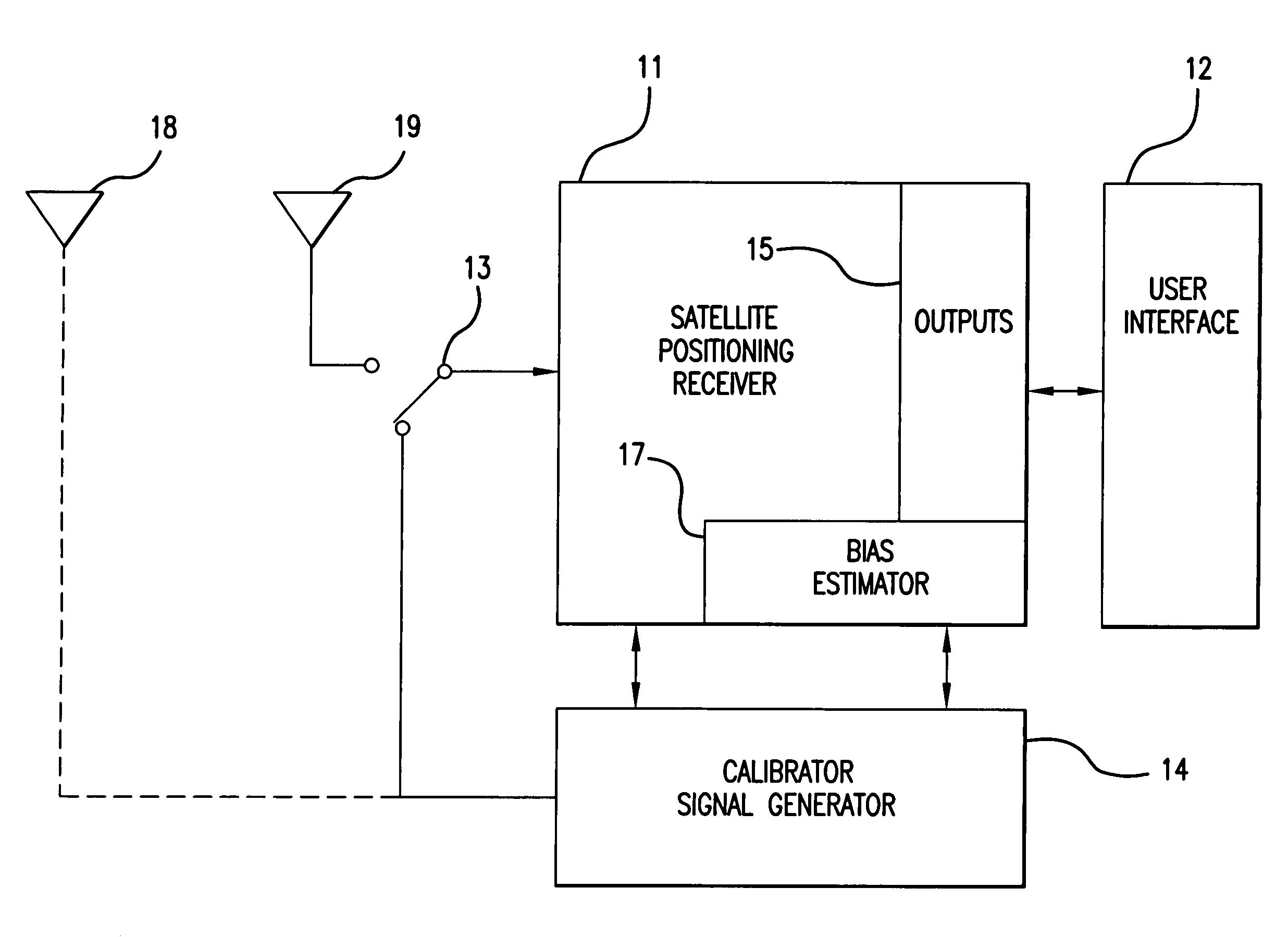
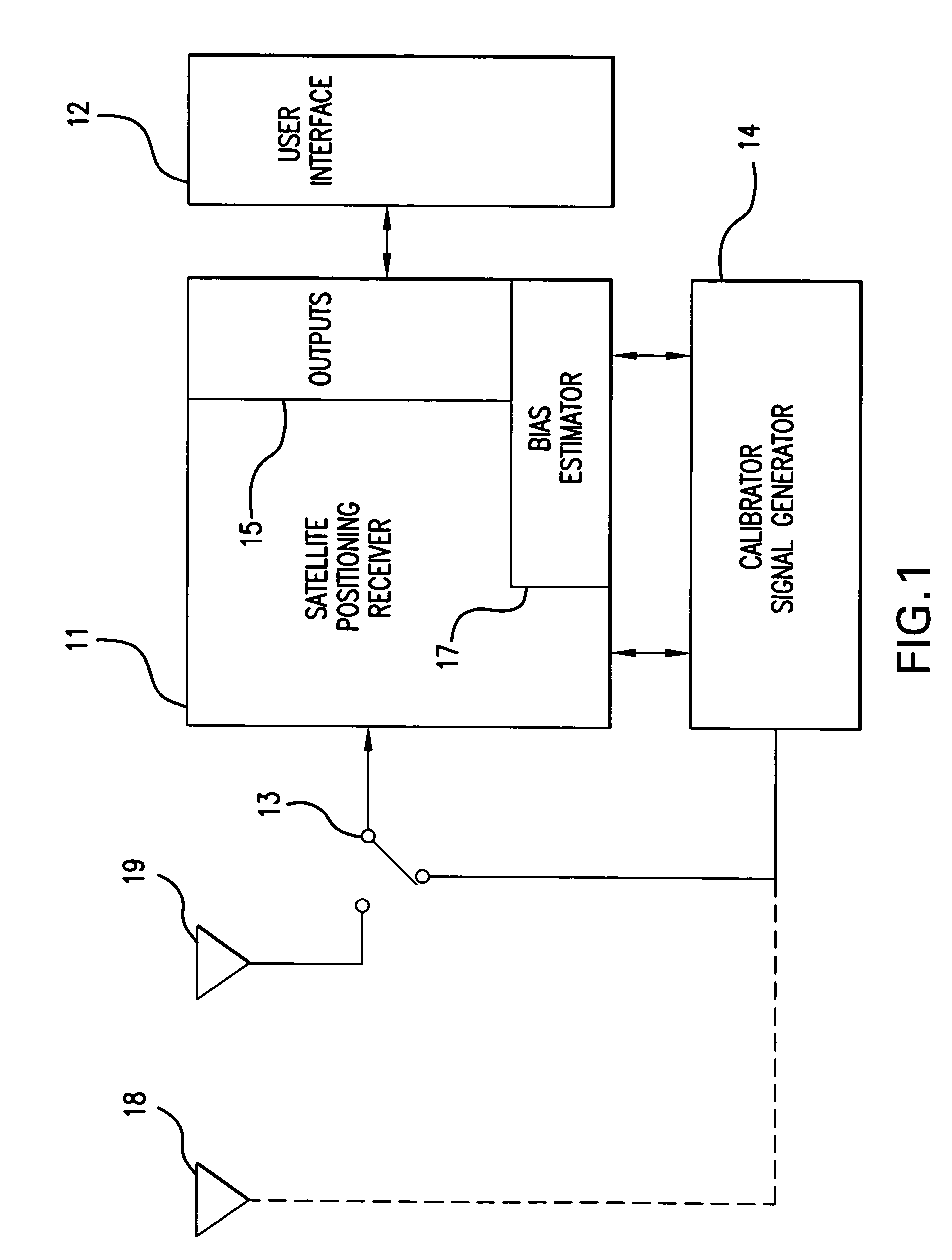
[0027]In the exemplary arrangement shown in FIG. 1, an improvement for calibrating a receiver 11 for a satellite positioning system, is shown. The satellite positioning system may be, for example, the global positioning system (GPS), the Russian global orbiting navigational satellite system (GLONASS) and / or future satellite positioning systems, such as the Galileo system and / or any other GNSS system.

[0028]The present invention incorporates replicas of synthetically generated calibration signals, at multiple frequencies, which are introduced at the input of the receiver 11. The corresponding relative delays measured by the receiver are thus determined as the receiver bias. For ionospheric estimation, for example, the calibration signal can have no...


PUM


Abstract

Calibrating a receiver for a satellite positioning system. At preset intervals, a plurality of calibration signals are generated and applied to the receiver. The plurality of calibration signals correspond to a plurality of satellite signals, respectively, from the satellite positioning system. A relative time-delay bias from a delay estimation algorithm within the receiver. The time-delay bias is stored, preferably with the receiver. The receiver receives the plurality of satellite signals from the satellite positioning system. The plurality of satellite signals are processed with the time-delay bias. The processing reduces effects from the satellite receiver and improving estimate of the differential delay and total electron content (TEC).

Description

RELATED PATENT APPLICATION[0001]This patent stems from a continuation application of U.S. patent application Ser. No. 11 / 175,008, and filing date of Jul. 5, 2005, now abandoned, entitled GPS RECEIVER WITH CALIBRATOR by inventors, Suman Ganguly, Aleksandar Jovancevic, and Andrew Brown. The benefit of the earlier filing date of the parent patent application is claimed for common subject matter pursuant to 35 U.S.C. § 120.BACKGROUND OF THE INVENTION[0002]The present invention relates to improving the accuracies of the satellite navigation receivers, such as those using the global positioning system (GPS), the Russian global orbiting navigational satellite system (GLONASS) and / or future Global Navigation Satellite (GNSS).DESCRIPTION OF THE RELEVANT ART[0003]In precision satellite positioning systems, the time delays between multiple frequencies, such as the L1 signal, L2 signal and L5 signal in GPS, are determined to account for the ionospheric delay. Receiver internal delays are of the...

Claims


Application Information

Patent Timeline
Patent Type & Authority Patents(United States)
IPC IPC(8): G01S1/00G01S19/21G01S19/26
CPCG01S19/23G01S19/32
Inventor GANGULY, SUMANJOVANCEVIC, ALEKSANDARBROWN, ANDREW
Owner CENT FOR REMOTE SENSING
Why Eureka
Try Eureka