Structure of gas sensor ensuring high degree of gas-tight seal

a technology of gas sensor and structure, which is applied in the field of gas sensor, can solve the problems of lack of adhesion between the housing and the sensor element, difficulty in uniform deformation of the annular extension, etc., and achieve the effect of facilitating crimping and facilitating crimping

Active Publication Date: 2007-05-29
DENSO CORP
View PDF13 Cites 8 Cited by
  • Summary
  • Abstract
  • Description
  • Claims
  • Application Information

AI Technical Summary

Benefits of technology

[0008]It is another object of the invention to provide an improved structure of a gas sensor which is designed to achieve desired crimping of a housing in order to ensure a higher degree of gas-tight seal between a measurement gas chamber and a reference gas chamber defined within the gas sensor.
[0010]The above structure of the housing allows the straight portion to be bent to approximately 90° with a uniform degree of deformation thereof. This causes the sealing member to be pressed tightly in a longitudinal direction of the housing, thereby establishing tight adhesion between the sensor element and the housing. This ensures a higher degree of the gas-tight seal between the reference gas chamber of the reference gas-exposed cover and the measurement gas chamber. The uniform degree of deformation of the straight portion is achieved even when a many time-used crimper that is worn greatly or the annular end portion of the housing has dimensional errors.
[0012]Specifically, when the thickness t1 is smaller than the thickness t4, it allows the straight portion to be deformed with little deformation of the annular neck. When the thickness t4 is smaller than the thickness t3, it facilitates ease of buckling the annular neck.
[0014]A relation of t1≦t2≦1.1×t1 may also be met. This allows the annular straight portion to have the outer diameter uniform in the longitudinal direction of the housing or to be tapered toward the tip thereof. This facilitates ease of crimping the annular straight portion.
[0015]If a length of the annular extension oriented to a longitudinal direction of the hollow cylindrical housing is defined as L1, and a length of the straight portion oriented to the longitudinal direction of the hollow cylindrical housing is defined as L2, a relation of 0.4×L1<L2<0.7×L1 may be met. This facilitates ease of crimping the annular straight portion.

Problems solved by technology

Specifically, the annular extension has greatly varying thickness, thus resulting in a difficulty in deforming the annular extension uniformly.
Particularly, use of a greatly worn crimper or dimensional errors in the annular extension results in a difficulty to bend the annular extension to 90°, which usually leads to a lack of adhesion between the housing and the sensor element, that is, gas-tight seal between the measurement gas chamber and the reference gas chamber.

Method used


Image

  • Structure of gas sensor ensuring high degree of gas-tight seal
  • Structure of gas sensor ensuring high degree of gas-tight seal
  • Structure of gas sensor ensuring high degree of gas-tight seal

Examples


Embodiment Construction

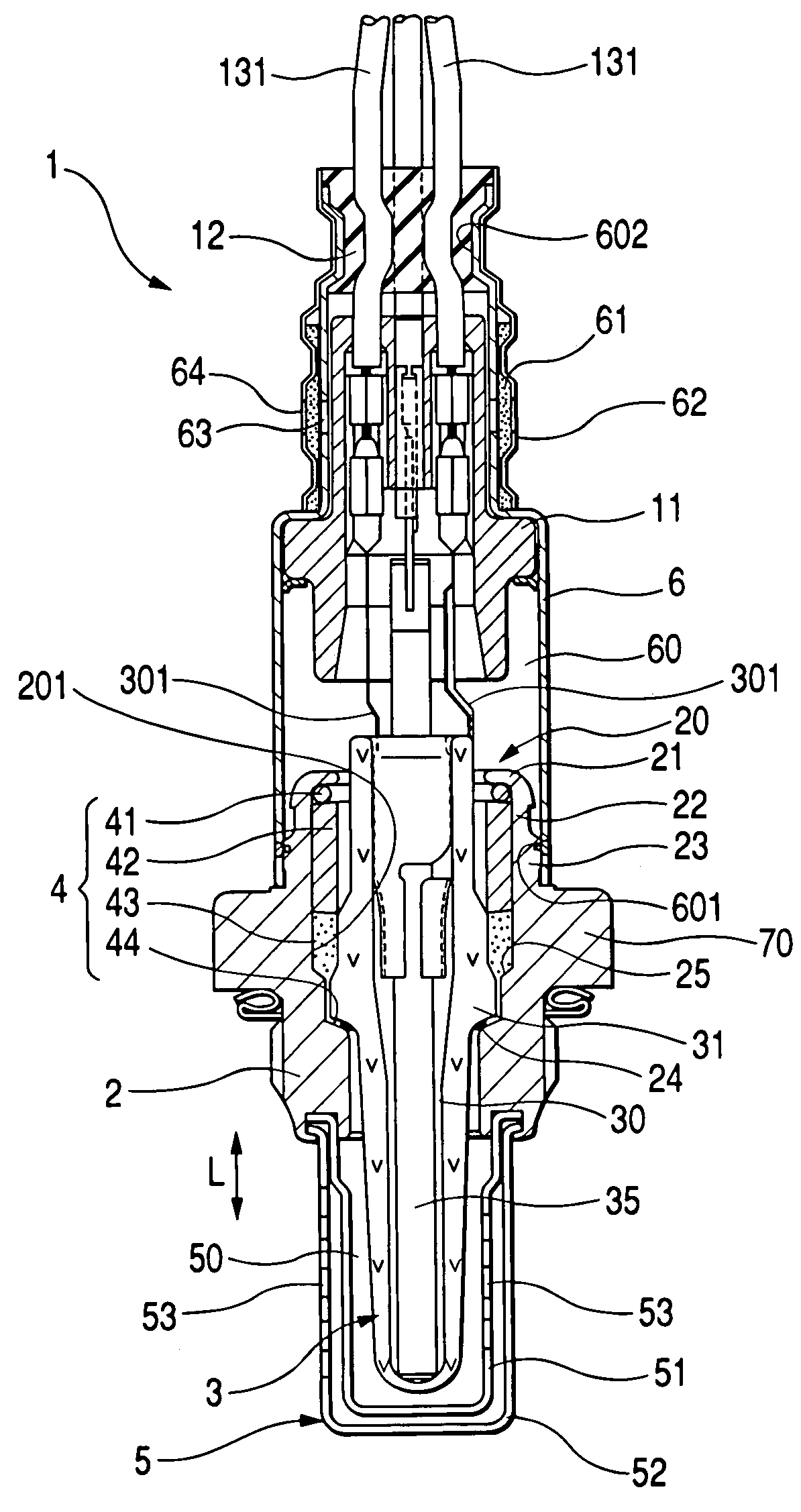
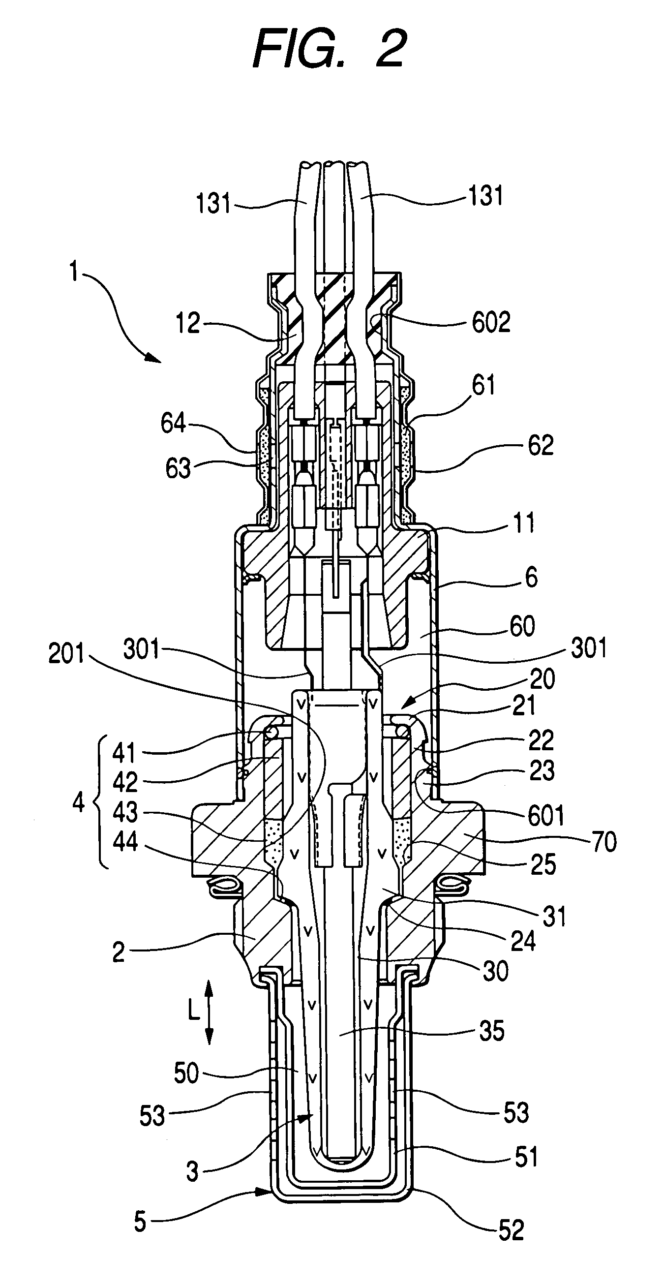
[0027]Referring to the drawings, wherein like reference numbers refer to like parts in several views, particularly to FIG. 2, there is shown a gas sensor 1 according to the invention which is designed to be installed in an exhaust system of an automotive internal combustion engine to measure an oxygen content in exhaust gasses for burning control of the engine. Note that the present invention is not limited to an oxygen sensor and may alternatively be used with a variety of gas sensors such as HC, CO, and NOx sensors.

[0028]The gas sensor 1 generally includes a sensing element 3, a hollow cylindrical housing 2, a measurement gas-exposed cover assembly 5, and an air-exposed cover 6. The housing 2 has formed therein an inner chamber 201 which is open at upper and lower ends, as viewed in the drawing. The sensor element 3 is retained within the inner chamber 201 of the housing 2. The measurement gas-exposed cover assembly 5 is joined at an end thereof to the lower end of the housing 2. ...


PUM

PropertyMeasurementUnit
crimp angleaaaaaaaaaa

Abstract

An improved structure of a gas sensor is provided which is designed for achieving desired crimping of an end portion of a sensor housing to establish a higher degree of gas-tight seal between the housing and a sensor element. The sensor element is fitted within the sensor housing. The end portion of the sensor housing is crimped or bent to urge the sensor element into constant abutment with an inner wall of the housing through a sealing member. The housing has an unique shape and dimensions selected to ensure the higher degree of gas-tight seal regardless of the degree of wear of a crimper and / or dimensional error of the housing.

Description

BACKGROUND OF THE INVENTION[0001]1. Technical Field of the Invention[0002]The present invention relates generally to a gas sensor which is installed, for example, in an exhaust system of automotive internal combustion engines to measure a specified component of exhaust emissions, and more particularly to an improved structure of such a gas sensor which is designed to ensure desired crimping of a sensor housing to establish a higher degree of gas-tight seal between the housing and a sensor element.[0003]2. Background Art[0004]Typical gas sensors installed in an exhaust system (e.g., an exhaust manifold or exhaust pipe) of automotive internal combustion engines are constructed to have a sensor element fitted hermetically within a hollow cylindrical housing. Such fitting is achieved by crimping or bending an open end portion of the housing to bring the sensor element into constant abutment with an inner wall of the housing. The sensor element has formed therein an inner chamber used as...

Claims


Application Information

Patent Timeline
Patent Type & Authority Patents(United States)
IPC IPC(8): G01N7/00G01N27/403G01N27/409G01N27/407
CPCG01N27/4071Y10T29/49007
Inventor TSUJI, NOBUYUKI
Owner DENSO CORP
Why Eureka
Try Eureka