
NMR spectrometer with refrigerator cooling

a spectrometer and refrigerator technology, applied in the field of nmr spectrometers, can solve the problems of high cost, inability to solve only the object of reducing or completely compensating for ln/sub>loss, and high cost, so as to reduce temperature loss, reduce temperature difference, and reduce energy loss

Active Publication Date: 2007-05-29
BRUKER SWITZERLAND AG
View PDF9 Cites 16 Cited by
  • Summary
  • Abstract
  • Description
  • Claims
  • Application Information

AI Technical Summary

Benefits of technology

The invention provides a cooling system for an NMR spectrometer that reduces the loss of cooling power and allows for efficient refueling of the helium tank and radiation shield. The cooling system includes additional cooling lines for the nitrogen tank and radiation shield, as well as a common refrigerator that cools all three objects. The cooling lines are designed to minimize temperature loss during transfer of the coolant. The system also includes a common thermally insulated section within the transfer lines to reduce temperature loss. The cooling circuits are operated with gaseous helium as coolant and may be individually adjusted through selection of the length of the contact surface between the transfer line and the regenerator. The refrigerator may also drive one or more of the cooling circuits. The cooling circuits form a helium circuit with at least one branch in the forward and / or return path. The invention provides a simple and cost-effective solution for cooling the NMR probe head and allows for efficient refueling of the helium tank and radiation shield.

Problems solved by technology

The thermal loss generated through thermal conduction and thermal radiation is therefore a problem.
Small units with low power also require different basic units such as e.g. compressors, and are therefore not inexpensive.
The expense required to solve only the object of reducing or completely compensating for the LN2 loss may therefore often be too high.

Method used


Image

  • NMR spectrometer with refrigerator cooling
  • NMR spectrometer with refrigerator cooling
  • NMR spectrometer with refrigerator cooling

Examples


Embodiment Construction

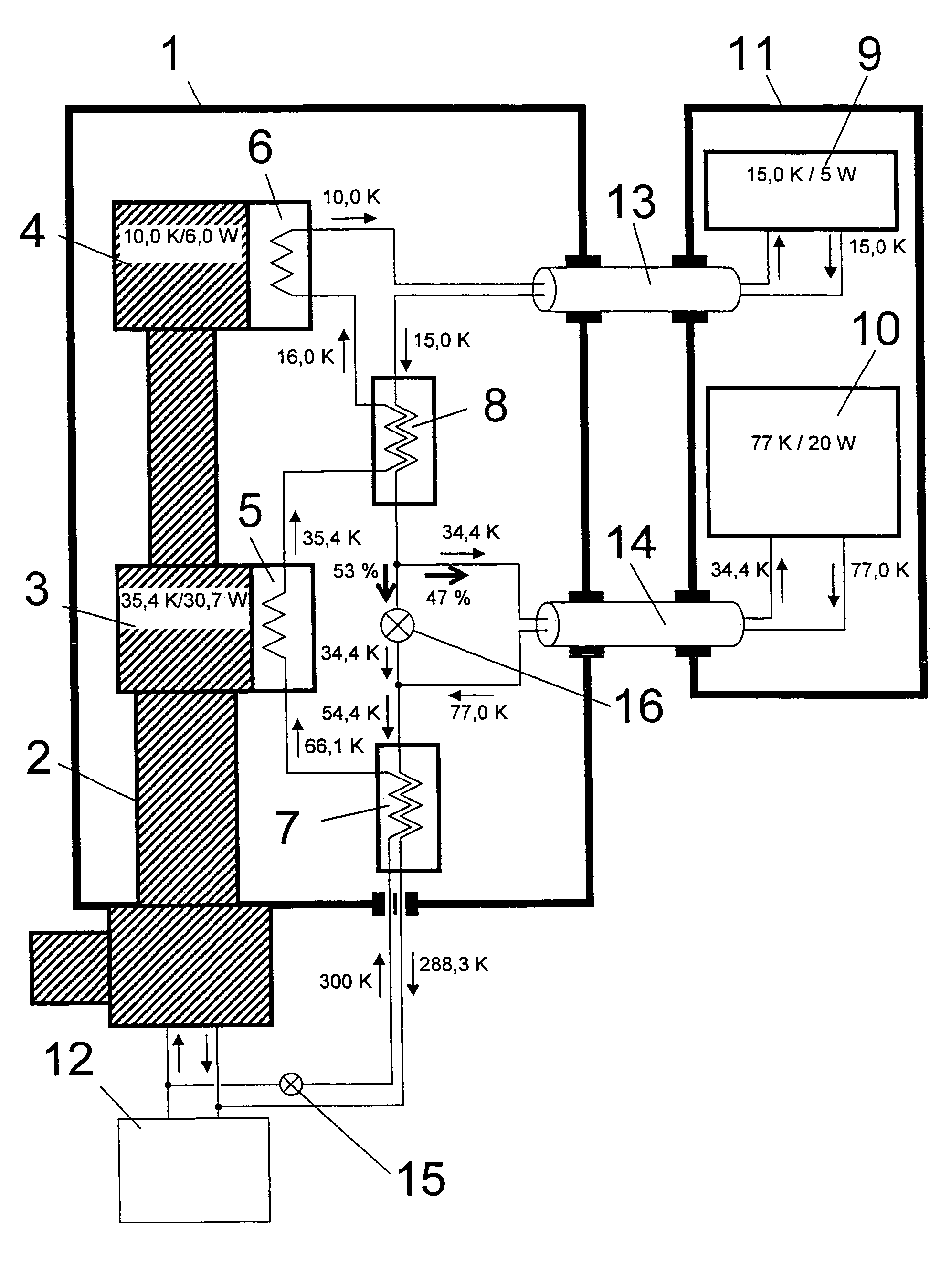
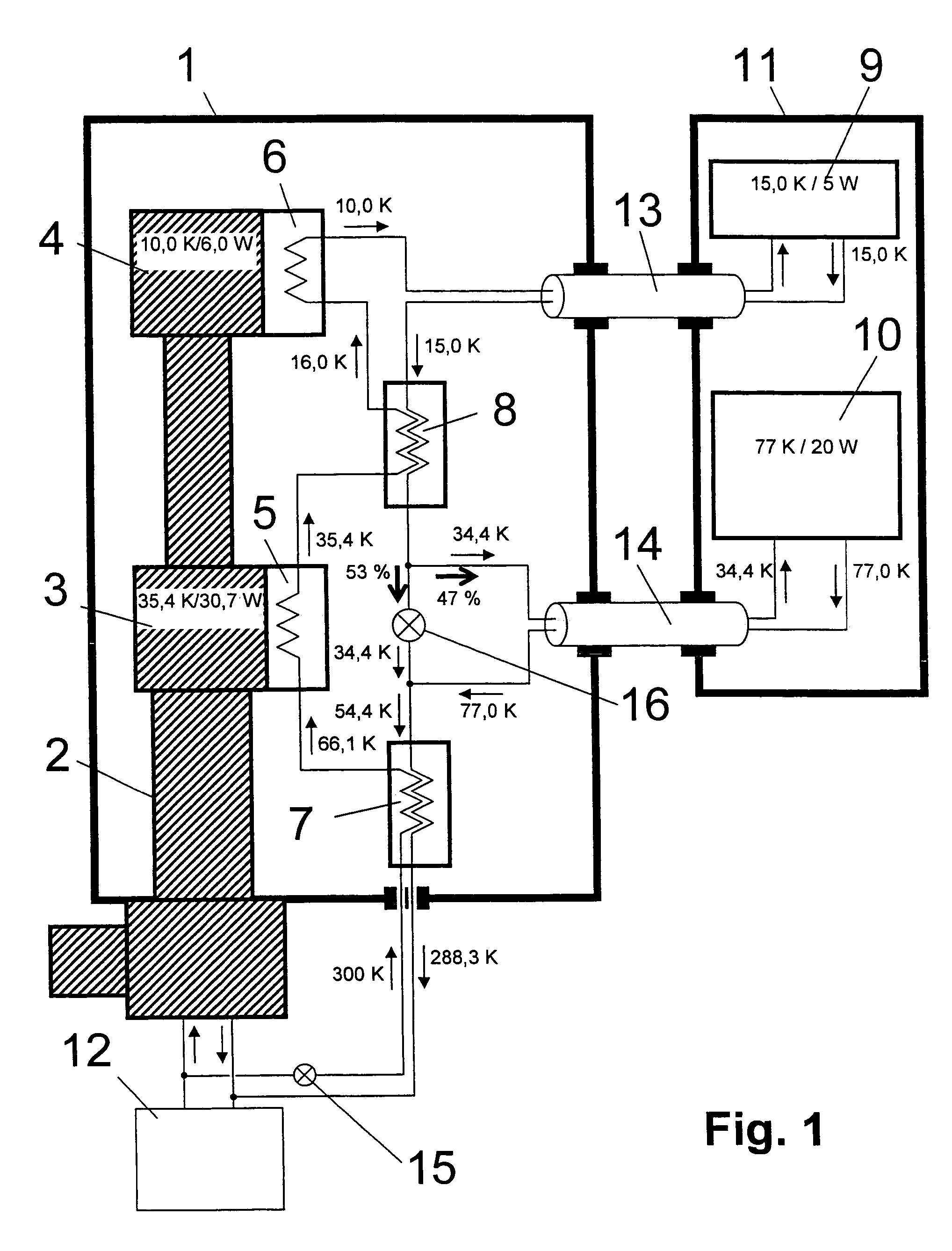
[0036]FIG. 1 shows a conventional cooling device comprising an evacuated and thermally insulated housing 1 which houses a refrigerator 2 with a first cold stage 3 and a second cold stage 4 and stage exchangers 5, 6 as well as counter current heat exchangers 7, 8. The cooling device cools an RF resonator 9 and a pre-amplifier 10 which are both parts of an NMR probe head 11. A similar variant is described in U.S. Pat. No. 5,889,456 which differs, however, in that the helium gas of the closed gas circuit is not circulated with a separate circulating pump but with the helium compressor 12 of the refrigerator 2 (similar to the U.S. Pat. No. 5,508,613).

[0037]Helium gas, which flows in one or more closed circuits, is used to transport the cooling power. The housing 1 and the NMR probe head 11 are connected to each other via transfer lines 13, 14, thereby closing the helium gas cooling circuit for cooling the RF resonator 9 and pre-amplifier 10. The NMR probe head 11 and the two transfer li...


PUM


Abstract

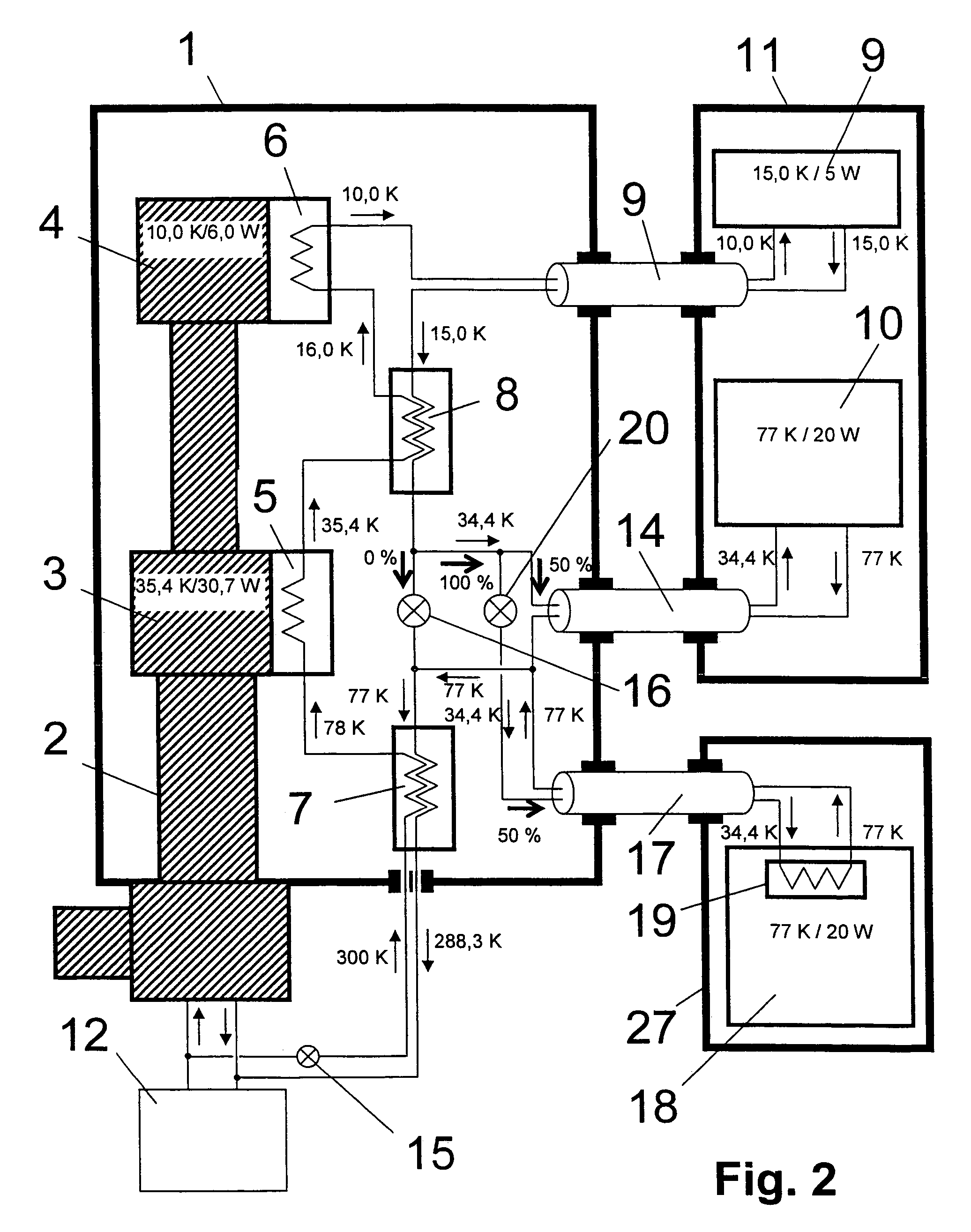
An NMR spectrometer comprising an NMR magnet system (27) disposed in a helium tank of a cryostat and an NMR probe head (11) disposed in a room temperature bore of the cryostat, which contains a cooled RF resonator (9) for receiving NMR signals from a sample to be investigated, and a cooled pre-amplifier (10), wherein the NMR probe head (11) is cooled by a common multi-stage compressor-operated refrigerator (2), wherein the refrigerator (2) comprises a cold head and several heat exchangers (5, 6) at different temperature levels, wherein the refrigerator (2) is disposed at a spatial separation from the cryostat in a separate, evacuated and thermally insulated housing (1) and wherein at least one cooling circuit with cooling lines, which are thermally insulated by a transfer line (13, 14) is disposed between the housing (1) containing the heat exchangers (5, 6) and the NMR probe head (11), is characterized in that additional cooling lines to an LN2 tank (18) or radiation shield (21) disposed in the cryostat and surrounding the helium tank are provided, and the refrigerator (2) also cools the LN2 tank (18) or the radiation shield (21). The inventive NMR spectrometer comprises a simple and inexpensive device for matching the holding time of LN2 to that of LHe through cooling the LN2 tank using the refrigerator provided for cooling the NMR probe head and without great expense.

Description

[0001]This application claims Paris Convention priority of DE 10 2004 053 973.1 filed Nov. 09, 2004 the complete disclosure of which is hereby incorporated by reference.BACKGROUND OF THE INVENTION[0002]The invention concerns an NMR spectrometer with an NMR magnet system disposed in the helium tank of a cryostat, and with an NMR probe head disposed in a room temperature bore of the cryostat which contains a cooled RF resonator for receiving NMR signals from a sample to be examined, and with a cooled pre-amplifier, wherein the NMR probe head is cooled by a common multi-stage compressor-operated refrigerator, the refrigerator comprising a cold head and several heat exchangers at different temperature levels, wherein the refrigerator is disposed at a spatial separation from the cryostat in a separate, evacuated and thermally insulated housing, and wherein at least one cooling circuit is provided comprising cooling lines, which are thermally insulated by a transfer line, extending betwee...

Claims


Application Information

Patent Timeline
Patent Type & Authority Patents(United States)
IPC IPC(8): F25B9/00
CPCF25D19/006G01R33/3804F25B9/10G01R33/34023G01R33/34092
Inventor TRIEBE, RENEMAREK, DANIELSCHETT, OSKARBAUMANN, DANIEL GUY
Owner BRUKER SWITZERLAND AG
Learn More