Connector and electronic apparatus having the same

a technology of electronic equipment and connectors, applied in the direction of threaded fasteners, screw connections, coupling devices, etc., can solve the problems of affecting the reliability of electrical connections, heating of connectors, and inability to meet the needs of use, so as to enhance the reliability of electric connections

Inactive Publication Date: 2007-05-29
KK TOSHIBA
View PDF20 Cites 23 Cited by
  • Summary
  • Abstract
  • Description
  • Claims
  • Application Information

AI Technical Summary

Benefits of technology

[0011]When the first and second connector bodies are individually fixed to the printed wiring boards by means of screws, mounting strength of the first and second connector bodies with respect to the printed wiring boards is increased. However, the positions of the first and second connector bodies remain constrained by means of merely fitting.
[0013]In particular, when a contact pressure between the lead terminals is low, an impact applied on the first and second connector bodies causes the lead terminals to vibrate, and sometimes to rub against each other. As a result, the plating layers on the surfaces of the lead terminals are shaved off, and metal powder produced by the shaving stays between the lead terminals as sludge. Consequently, contact resistance between the lead terminals is increased, thereby inducing a problem of heating of the connector or occurrence of faulty continuity.
[0016]The present invention aims at providing a connector which can ensure sufficient mounting strength of the first and second connector bodies with respect to the first and second printed wiring boards, and can reduce stress applied on the contact portion between the lead terminals, to thus enhance reliability of electric connection; as well as a method for holding the connector.
[0021]According to the invention, a load for preventing relative movement between the first printed wiring board, the second printed wiring board, the first connector body, and the second connector body can be applied, thereby providing firm restraint. Therefore, damage which may be otherwise be inflicted on the soldered portions between the first and second printed wiring boards and the lead terminals can be prevented, and stress applied on a contact portion between lead terminals can be reduced, thereby enhancing reliability of electric connection.

Problems solved by technology

Therefore, when, for instance, a strong impact, or stress resulting from a difference in thermal expansion is exerted on a fit portion between the first connector body and the second connector body, inevitably unbearable force is applied on a contact portion between the lead terminals.
Consequently, contact resistance between the lead terminals is increased, thereby inducing a problem of heating of the connector or occurrence of faulty continuity.

Method used


Image

  • Connector and electronic apparatus having the same
  • Connector and electronic apparatus having the same
  • Connector and electronic apparatus having the same

Examples


first embodiment

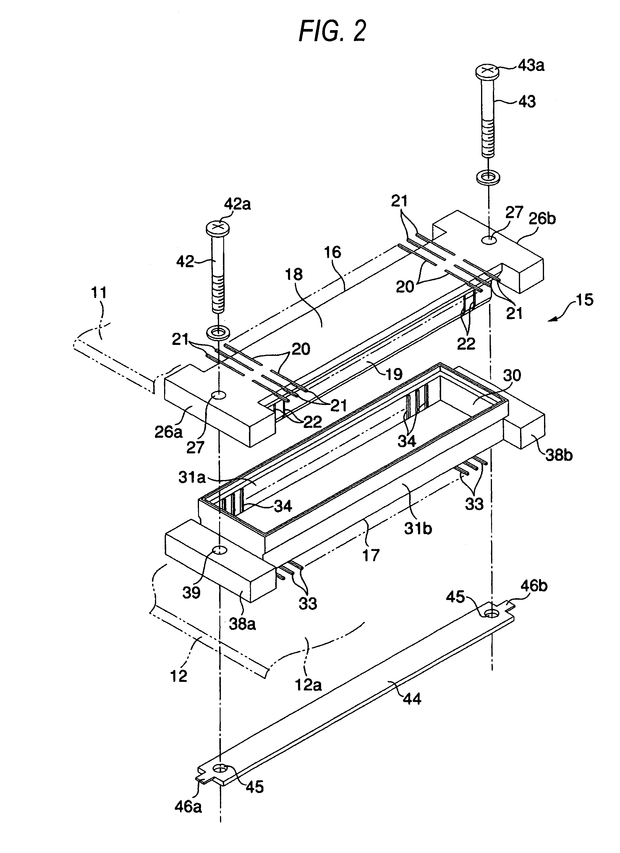
[0039]Hereinbelow, the invention will be described by reference to FIGS. 1 to 5.

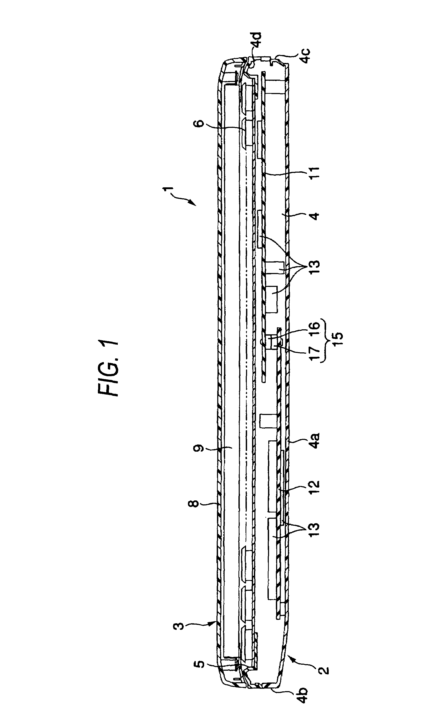
[0040]FIG. 1 shows a portable computer 1, which is an example of an electronic apparatus. The portable computer 1 comprises a computer main body 2, and a display unit 3 supported by the computer main body 2. The computer main body 2 has an enclosure 4. The enclosure 4 has the geometry of a flat box having a bottom wall 4a, left and right side walls 4b and 4c, and an upper wall 4d. A keyboard support section 5 is formed on the upper wall 4d. The keyboard support section 5 supports a keyboard 6.

[0041]The display unit 3 comprises a display housing 8, and a liquid crystal display device 9 contained in the display housing 8. The display unit 3, which is connected to a rear end of the enclosure 4 by way of an unillustrated hinge, is pivotable between a closed position and an open position. At the closed position, the display unit 3 is laid on the enclosure 4 in such a manner as to cover the keyboard 6 from abo...

second embodiment

[0072]FIGS. 6 and 7 show the invention.

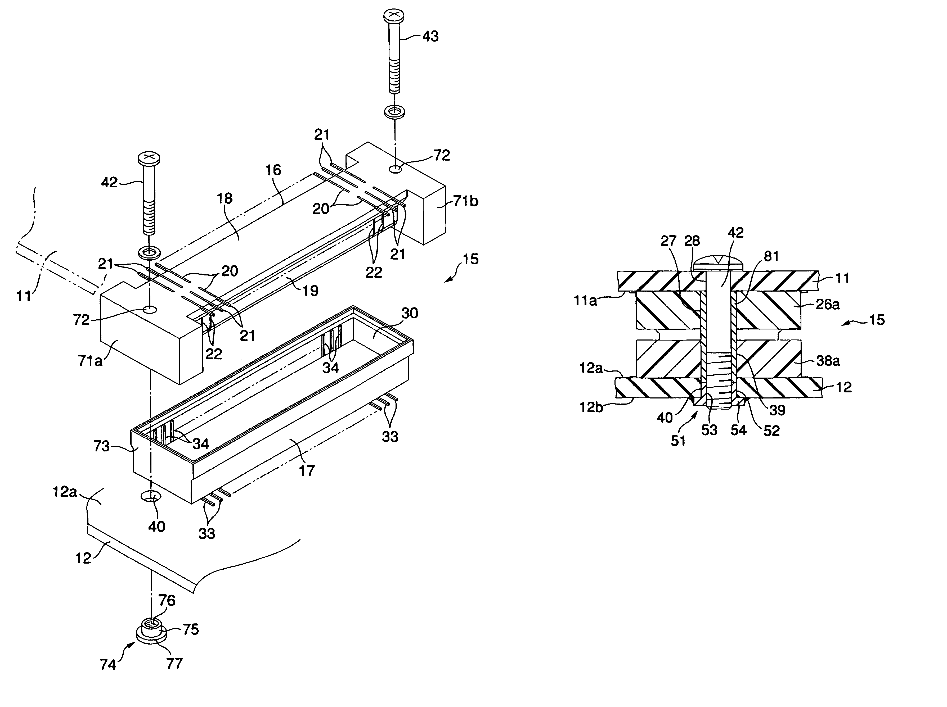
[0073]In the second embodiment, a nut 51 is employed as a fastening member. However, in other respects, the stacking connector 15 is identical in configuration with that of the first embodiment. Hence, elements identical with those of the first embodiment are denoted by the same reference numerals, and repeated descriptions are omitted.

[0074]FIG. 6 shows a coupling portion between the screw-receiving section 26a of the first connector body 16 and the screw-receiving section 38a of the second connector body 17. The nut 51 has a cylinder section 52 to be fitted in the insertion hole 40 in the second printed wiring board 12. A female thread 53 is formed in an inner face of the cylinder section 52.

[0075]The cylinder section 52 has a flange 54. The flange 54 projects radially outward from one end of the cylinder section 52, and overlaps the lower face 12h of the second printed wiring board 12. A periphery of the flange 54 is fixedly mounted directly...

third embodiment

[0077]FIGS. 8 and 9 show the invention.

[0078]The third embodiment differs from the first embodiment in configuration of restraint for preventing relative movement between the first printed wiring board 11, the second printed wiring board 12, and the stacking connector 15. In other respects, the stacking connector 15 is identical in basic configuration with that of the first embodiment.

[0079]FIG. 8 shows the screw-receiving sections 26a and 38a of the first and second connector bodies 16 and 17. The screw-receiving section 38a of the second connector body 17 has a first section 61a and a second section 61b. The first and second sections 61a and 61b are aligned in a direction crossing the longitudinal direction of the second connector body 17.

[0080]A first screw hole 62 is formed in the first section 61a of the screw-receiving section 38a. The first screw hole 62 is continuous with the insertion hole 28 in the first printed wiring board 11. A second screw hole 63 is formed in the seco...


PUM


Abstract

A connector includes: a first connector body having a plurality of first lead terminals soldered onto a first wiring board; a second connector body having a plurality of second lead terminals soldered onto a second wiring board; a screw member; and a fastening member engageable to the screw member. The first connector body and the second connector body are engaged with each other to bring the first lead terminals and the second lead terminals into contact such that the first lead terminals and the second terminals electrically connect the first wiring board to the second wiring board. The first and second wiring boards and the first and second connector bodies are integrally fastened together by engaging the screw member to the fastening member.

Description

[0001]This application is based upon and claims the benefit of priority from prior Japanese Patent Application No. 2004-267243, filed Sep. 14, 2004, the entire contents of which are incorporated herein by reference.BACKGROUND OF THE INVENTION[0002]1. Field of the Invention[0003]The present invention relates to a connector which is interposed between two opposing wiring boards and which electrically connects the wiring boards to each other, as well as to a method for holding the connector unit between wiring boards. Furthermore, the invention relates to an electronic apparatus, such as a portable computer, having the connector.[0004]2. Background Art[0005]In an electronic apparatus, such as a portable computer or a cellular phone, two printed wiring boards disposed so as to face each other are electrically connected together by way of a connector known as a stacking connector.[0006]The connector has a first connector body mounted on one printed wiring board and a second connector bod...

Claims


Application Information

Patent Timeline
Patent Type & Authority Patents(United States)
IPC IPC(8): H01R12/00
CPCH01R13/6215H01R12/716
Inventor NAKAJIMA, YUJIKAJI, KENJI
Owner KK TOSHIBA
Why Eureka
Try Eureka