Piezoelectric element, composite piezoelectric element, and filter, duplexer and communication equipment using the same

a composite piezoelectric element and piezoelectric element technology, applied in piezoelectric/electrostrictive/magnetostrictive devices, piezoelectric/electrostriction/magnetostriction machines, electrical apparatus, etc., can solve the problems of spurious response, laterally propagating acoustic wave modes cannot be sufficiently suppressed, and spurious response can be effectively suppressed, so as to improve piezoelectric effect and improve piezoelectric

Inactive Publication Date: 2007-05-29
PANASONIC CORP
View PDF10 Cites 18 Cited by
  • Summary
  • Abstract
  • Description
  • Claims
  • Application Information

AI Technical Summary

Benefits of technology

[0018]Therefore, an object of the present invention is to provide an improved piezoelectric element with which spurious responses can be suppressed effectively. Another object of the present invention is to provide an improved piezoelectric element that has good vibration characteristics. Another object of the present invention is to provide a piezoelectric element having excellent mechanical strength. Furthermore, another object of the present invention is to provide an improved composite piezoelectric element so that unwanted vibration modes do not interfere with each other between the adjacent piezoelectric elements. Furthermore, another object of the present invention is to provide a filter, a duplexer and communication equipment using such a piezoelectric element or composite piezoelectric element.

Problems solved by technology

Therefore, spurious responses tend to occur.
These laterally propagating acoustic wave modes are unwanted vibration modes.
Furthermore, in the case of a composite piezoelectric element in which piezoelectric elements are arranged adjacent to each other, unwanted vibration modes interfere with each other between the adjacent piezoelectric elements, which causes spurious response.
However, the piezoelectric vibrating portion 80 is supported at symmetric positions with respect to the substrate 81, so that in particular, the laterally propagating acoustic wave modes cannot sufficiently be suppressed.
However, similarly to the above example, the piezoelectric vibrating portion 60 is supported at symmetric positions with respect to the substrate 61, so that in particular, the laterally propagating acoustic wave modes cannot sufficiently be suppressed.
The confined vibration mode causes spurious responses.
Thus, in the conventional piezoelectric element shown in FIGS. 29A and 29B, spurious responses cannot be suppressed effectively.

Method used


Image

  • Piezoelectric element, composite piezoelectric element, and filter, duplexer and communication equipment using the same
  • Piezoelectric element, composite piezoelectric element, and filter, duplexer and communication equipment using the same
  • Piezoelectric element, composite piezoelectric element, and filter, duplexer and communication equipment using the same

Examples


first embodiment

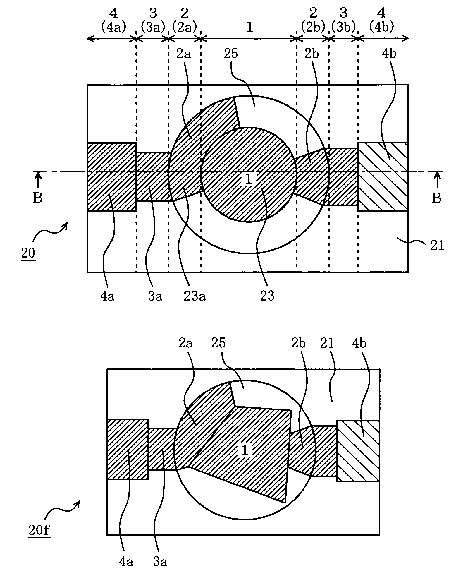
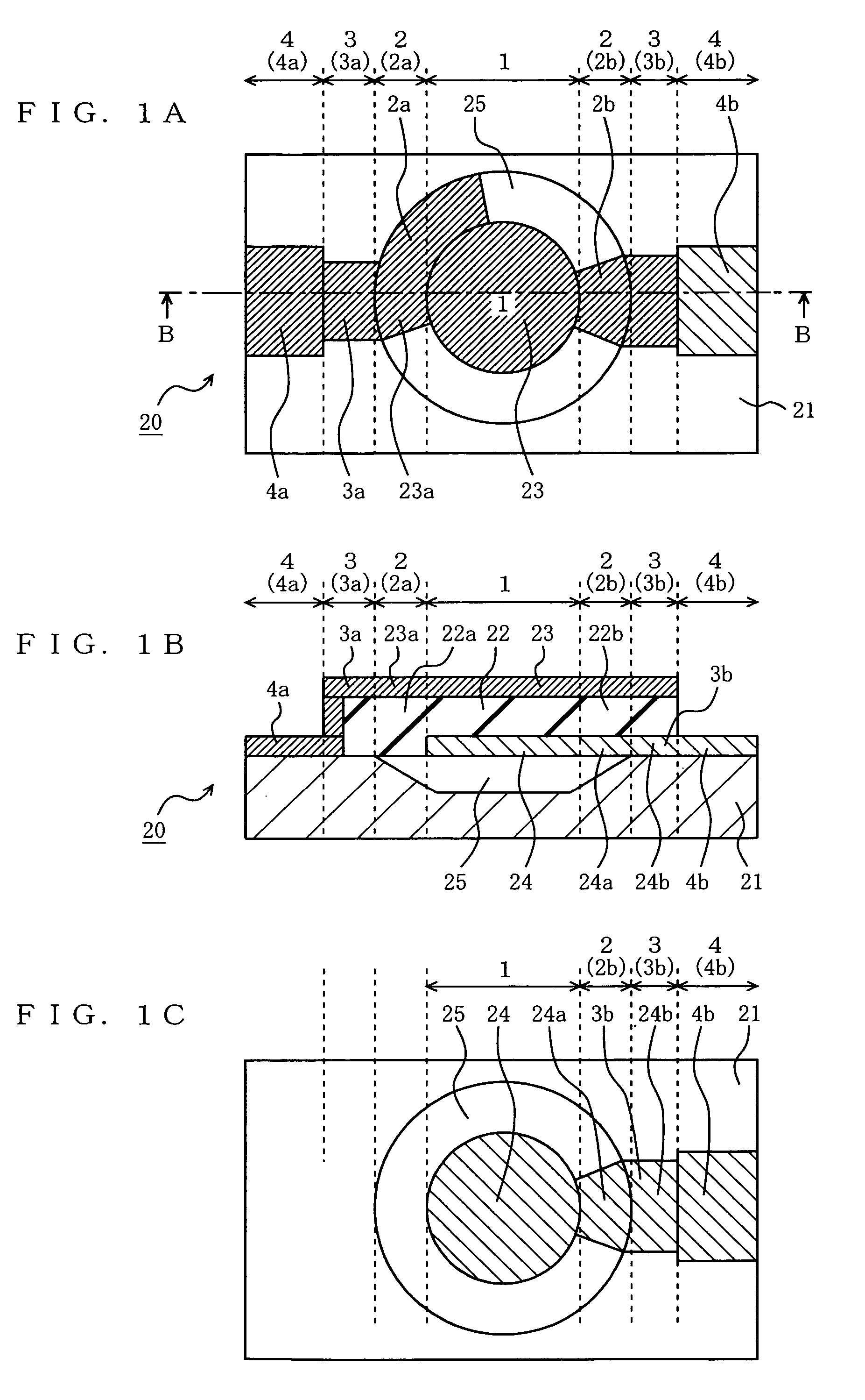
[0108]FIG. 1A is a top view of a piezoelectric element 20 of a first embodiment of the present invention. FIG. 1B is a cross-sectional view taken along the line B-B in FIG. 1A of the piezoelectric element 20 of the first embodiment. FIG. 1C is a plan view of an extracted portion of a lower electrode layer and its vicinity.

[0109]In FIGS. 1A to 1C, the piezoelectric element 20 includes a piezoelectric vibrating portion 1, two bridging portions 2 (2a, 2b), two wiring electrode portions 3 (3a, 3b), and two terminal electrode portions 4 (4a, 4b).

[0110]The piezoelectric vibrating portion 1 includes a lower electrode layer 24 laminated on a substrate 21, a piezoelectric layer 22 laminated on the lower electrode layer 24, and an upper electrode layer 23 laminated on the piezoelectric layer 22. The piezoelectric vibrating portion 1 is provided above a cavity portion 25 formed on the surface of the substrate 21. The material of the piezoelectric layer 22 is a suitable piezoelectric material s...

second embodiment

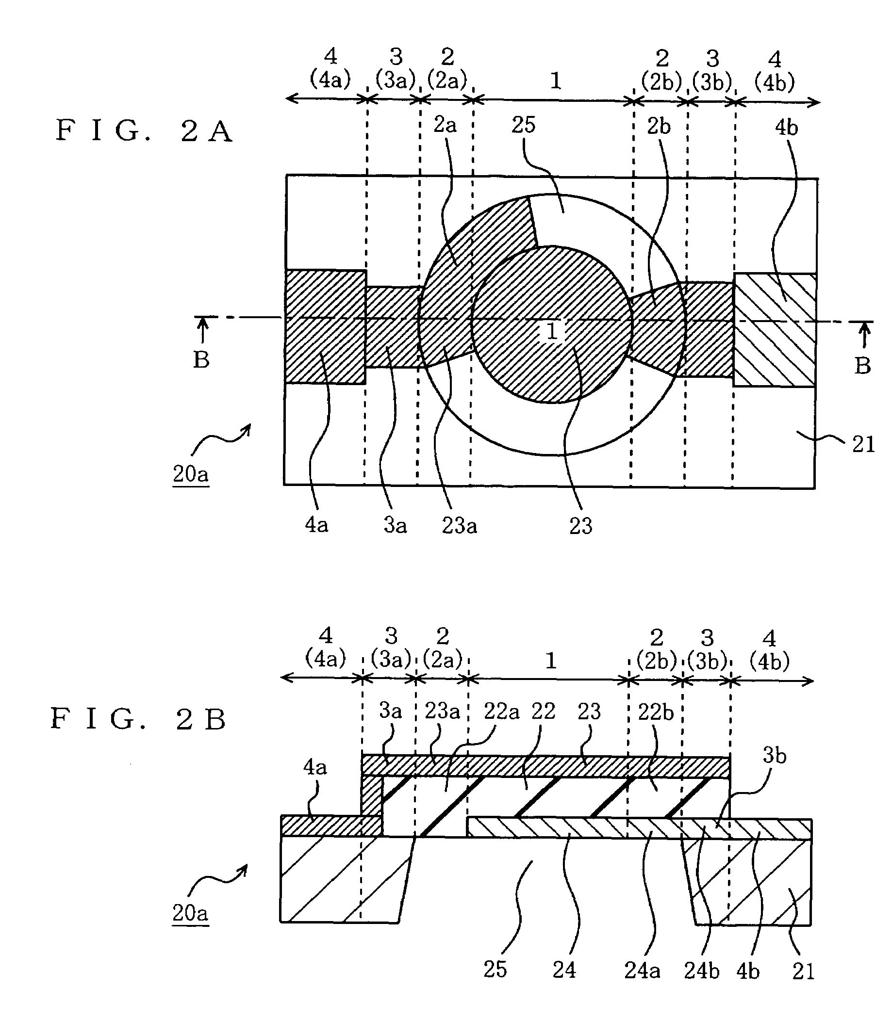
[0125]FIG. 4A is a top view of a piezoelectric element 20c of a second embodiment of the present invention. FIG. 4B is a view showing a first example of the cross-section taken along the line X-X in FIG. 4A of the piezoelectric element 20c of the second embodiment. FIG. 4C is a view showing a second example of the cross-section taken along the line X-X in FIG. 4A of the piezoelectric element 20c of the second embodiment. FIG. 4D is a view showing a third example of the cross-section taken along the line X-X in FIG. 4A of the piezoelectric element 20c of the second embodiment.

[0126]As shown in FIG. 4B, in the first example, the piezoelectric element 20c is provided additionally with a dielectric layer 7a between the lower electrode layer 24 and the substrate 21. When the substrate 21 is a semiconductor such as a silicon substrate, the dielectric layer 7a functions as an insulating substrate. Since the dielectric layer 7a is added to the components constituting the first and the secon...

third embodiment

[0131]The third embodiment of the present invention is a variant example of the first embodiment of the present invention.

[0132]FIG. 5A is a view showing a first example of the cross-section of the piezoelectric element 20d of the third embodiment. In the first embodiment, as shown in FIG. 1B, the lower electrode layer 24 does not straddle the cavity portion 25. On the other hand, in the first example of the third embodiment, as shown in FIG. 5A, the lower electrode layer 24 includes a portion 24c. In other words, the lower electrode layer 24 is formed so as to straddle the cavity portion 25. With this configuration, the mechanical strength of the first bridging portion 2a can be increased. In addition, the capacitance of the capacitor can be adjusted by extending the lower electrode layer 24 to increase the area in which the upper electrode layer 23 opposes the lower electrode layer 24.

[0133]FIG. 5B is a view showing a second example of the cross-section of the piezoelectric elemen...


PUM


Abstract

A piezoelectric element of the present invention includes a substrate, a lower electrode layer, a piezoelectric layer, an upper electrode layer, a cavity portion formed below a piezoelectric vibrating portion, and at least two bridging portions. The at least two bridging portions are formed so as not to be line-symmetric with respect to any line segment traversing the piezoelectric vibrating portion and / or so as not to be point-symmetric with respect to any point in the piezoelectric vibrating portion in a projection of the piezoelectric vibrating portion in the laminating direction.

Description

BACKGROUND OF THE INVENTION[0001]1. Field of the Invention[0002]The present invention relates to a piezoelectric element, more specifically, an improved piezoelectric element having good vibration characteristics in which unwanted signals based on unwanted vibrations (hereinafter, referred to as “spurious responses”) are suppressed effectively. The present invention also relates to an improved composite piezoelectric element in which unwanted vibration modes do not interfere with each other between adjacent piezoelectric elements. The present invention also relates to a filter, a duplexer and communication equipment using the same.[0003]2. Description of the Background Art[0004]There is a demand for increasingly smaller and lighter components to be integrated in electronic equipment, in particular portable equipment. For example, for filters used in portable equipment, there is a demand for compactness, small insertion loss and large attenuation characteristics.[0005]Filters using a...

Claims


Application Information

Patent Timeline
Patent Type & Authority Patents(United States)
IPC IPC(8): H01L41/047H03H9/02H03H9/13H03H9/17H03H9/58
CPCH03H9/02094H03H9/02118H03H9/173H03H9/174H03H9/175H03H9/587H03H9/588H03H9/589
Inventor ONISHI, KEIJINAKAMURA, HIROYUKINAKATSUKA, HIROSHI
Owner PANASONIC CORP
Why Eureka
Try Eureka