
Conductive adhesive and piezoelectric device using it

A technology for conductive adhesives and piezoelectric components, which is applied in conductive adhesives, non-polymer adhesive additives, electrical components, etc., and can solve elastic deformation, large subsidence of SAW components, and inability to obtain a joint state, etc. problem to ensure wire bonding and reduce sag

Inactive Publication Date: 2005-02-16
SEIKO EPSON CORP
View PDF3 Cites 9 Cited by
  • Summary
  • Abstract
  • Description
  • Claims
  • Application Information

AI Technical Summary

Problems solved by technology

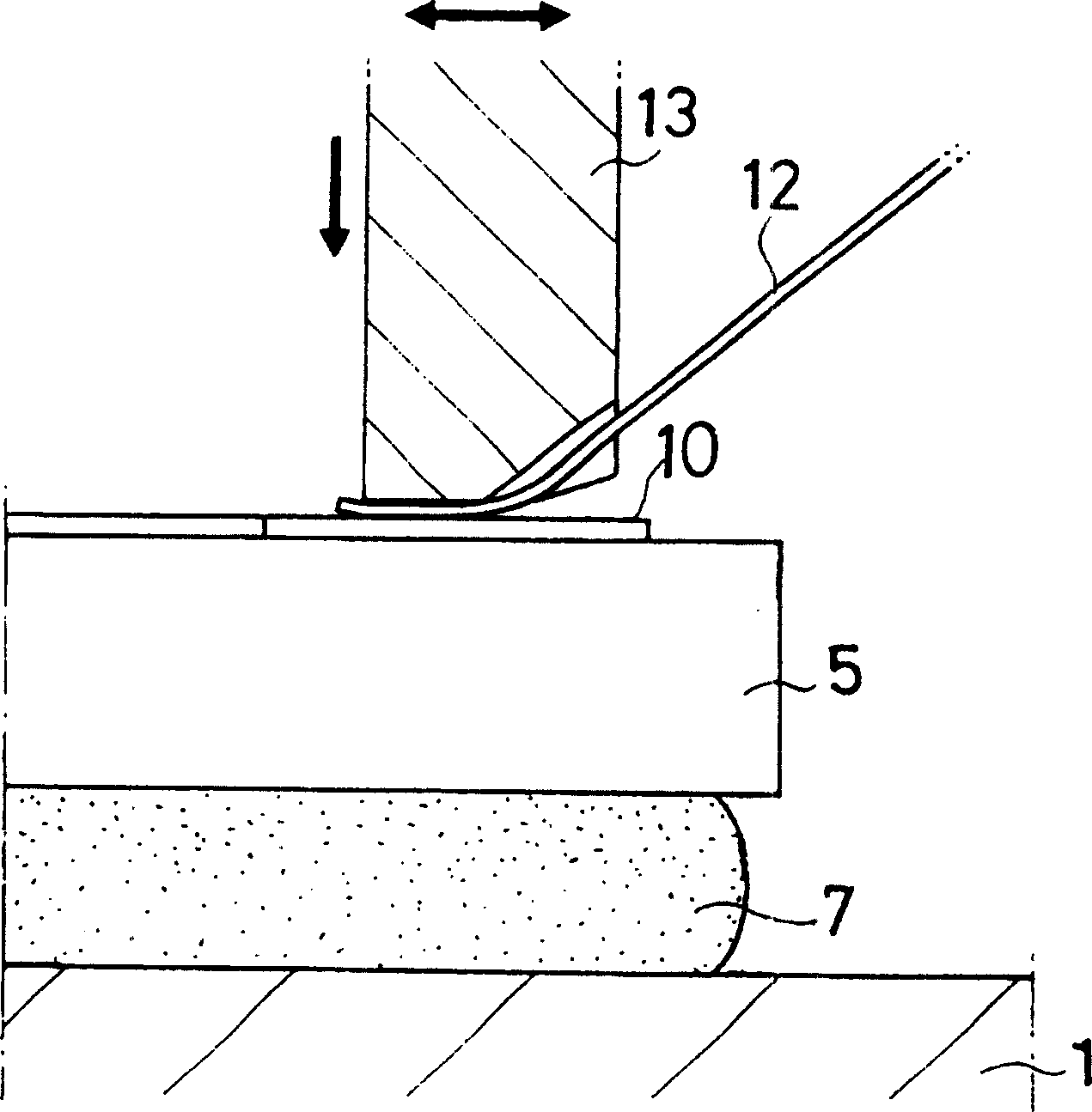
[0010] When using a wedge-shaped tool to press the end of the bonding wire against the surface of the bonding area, this elastic conductive adhesive may cause unnecessary elastic deformation, resulting in a large sagging of the SAW element
The bonding state of the bonding wire formed by the wedge welding method is affected by the output of ultrasonic waves, the load applied to the bonding wire, the processing time, and the balance of these factors, so if the SAW element sinks too much, the load applied to the bonding wire and ultrasonic vibration disappear, causing a problem that a good bonding state cannot be obtained

Method used


Image

  • Conductive adhesive and piezoelectric device using it
  • Conductive adhesive and piezoelectric device using it
  • Conductive adhesive and piezoelectric device using it

Examples


Embodiment 1

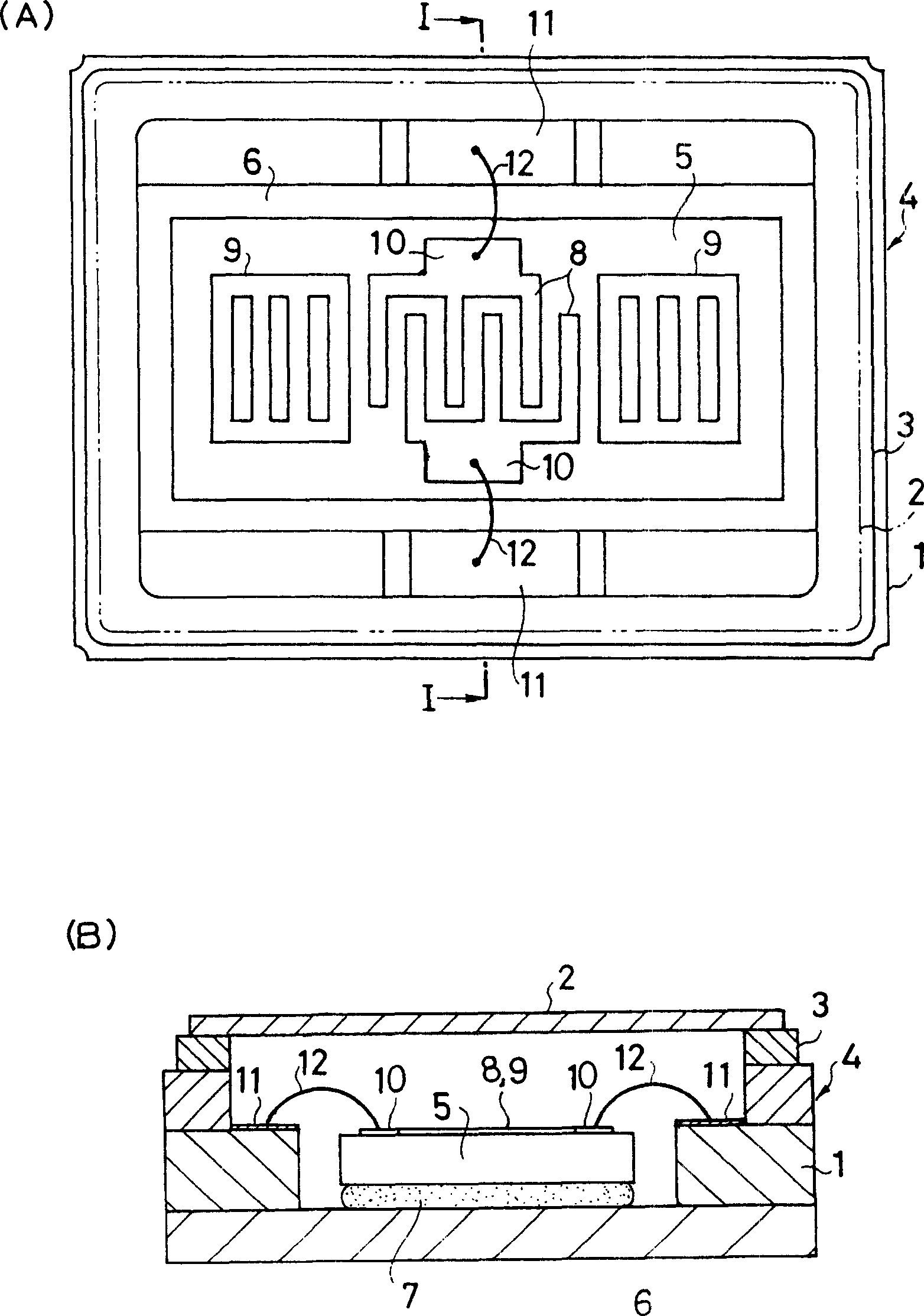
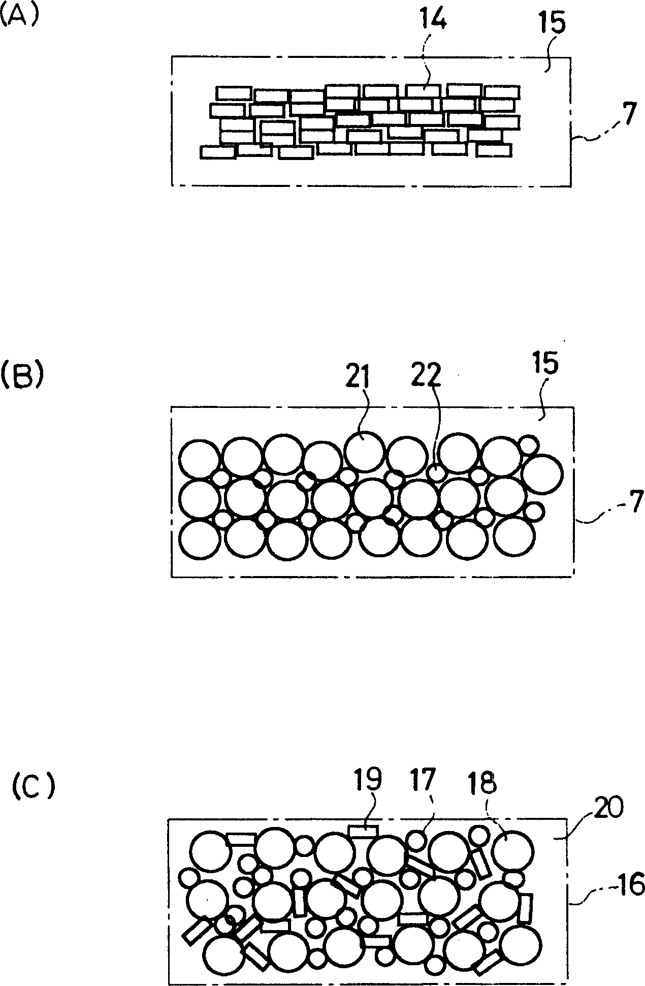
[0045] Use respectively with image 3 (A) The conductive adhesive of the first embodiment of the present invention related to the above. image 3 (B) The Conductive Adhesive of the Second Example Related to the Above A SAW resonator in which a SAW element was bonded and fixed was produced (this Example 2). When bonding SAW components to the base mounting surface, the die fixing conditions, that is, the pressing force is 20+ / -15g / cm 2 , The hardening conditions of the conductive adhesive are: the present embodiment 1 is 180 ° C × 1 hour of N2 drying, and the present embodiment 2 is 280 ° C × 3 hours of vacuum drying. An Al / Si1% bonding wire with a diameter of 40 μm was used as the bonding wire, and wedge welding was performed using a commercially available fully automatic ultrasonic wedge welding machine under the conditions of a processing time of 20 ms, an ultrasonic output of 150 W, and an applied force of 50 g. As a comparative example, the structure is the same as that o...


PUM

PropertyMeasurementUnit
lengthaaaaaaaaaa
diameteraaaaaaaaaa
diameteraaaaaaaaaa

Abstract

In an SAW device in which an SAW element (5) is mounted on a base (1) of a package (4) with its bonding pads (10) and connection terminals (11) of the package connected by bonding wires, a lid (2) is joined to the base (1) by seam welding to be hermetically sealed. The SAW element (5) is bonded and affixed to a mounting surface (6) of the base (1) by using a conductive adhesive (7) which contains 80 to 85 wt.% of a resin material and 20 to 15 wt.% of a flaky conductive filler, or a conductive adhesive which contains an 82.5 to 85 wt.% of a resin material and 17.5 to 15 wt.% of a conductive filler, the conductive filler comprising 30 wt.% of a small particulate conductive filler and 70 wt.% of a large particulate conductive filler.

Description

technical field [0001] The present invention relates to a structure of a piezoelectric device in which a piezoelectric element such as a surface acoustic wave (SAW: surface acoustic wave) element is bonded and fixed in a package, and a conductive adhesive suitable for bonding the piezoelectric element. Background technique [0002] Patent Document 1: JP-A-2003-110401 [0003] Patent Document 2: Japanese Unexamined Patent Publication No. 6-177701 [0004] Patent Document 3: JP-A-2002-16476 [0005] Conventionally, SAW devices such as resonators, filters, and oscillators using SAW elements having an IDT (Interdigital Transition devices) and reflectors, and use surface acoustic waves excited by the IDT. In particular, recently, in the field of communication equipment and the like, high frequency and high precision of SAW devices that are compatible with high-speed communication are required. [0006] Generally, a SAW device has a case in which a metal cover is hermetically ...

Claims


Application Information

Patent Timeline
Patent Type & Authority Applications(China)
IPC IPC(8): C09J9/02C09J11/04C09J201/00H01B1/00H01B1/22H01L21/52H03H9/02H03H9/05H03H9/25
CPCH03H9/1071H01L2224/45124H01L2224/4847H01L2224/48091H01L2224/73265H03H9/0585H01L2224/85181H01L2924/16195H01L2924/00014H01L2924/00H01L21/52
Inventor 井口修一
Owner SEIKO EPSON CORP
Learn More