Component mounting apparatus including a polishing device

a technology of mounting apparatus and polishing device, which is applied in the direction of non-electric welding apparatus, auxillary devices, welding/cutting auxillary devices, etc., can solve the problems of stainless steel suction nozzles with relatively short operational life, ic chips cracking or failing to be bonded with the required shear strength, etc., to achieve good vibration characteristics and improve abrasive wear resistance

Inactive Publication Date: 2007-05-22
PANASONIC CORP
View PDF43 Cites 12 Cited by
  • Summary
  • Abstract
  • Description
  • Claims
  • Application Information

AI Technical Summary

Benefits of technology

[0011]An object of the present invention is to provide a suction nozzle which exhibits good vibration characteristics and of which working face has improved abrasive wear resistance, and a method and apparatus of mounting components using this suction nozzle, in which a component is mounted on an object by ultrasonic-bonding their respective metal interconnects, and when necessary, the working face of suction nozzle is refined quickly using the ultrasonic vibration for the ultrasonic bonding so that mounting operation can be continued without long interruptions.
[0013]This suction nozzle is used in a component mounting method wherein metal interconnects of a component and an object are bonded by friction by applying ultrasonic vibration to a point between the support point of rockable suction nozzle and its working face. The hardened layer or the suction head made of cemented carbide hardly affects the vibration characteristics and vibration transmission characteristics of the suction nozzle, since the suction nozzle is mainly made of stainless steel and its working face is formed to have a predetermined roughness. The above ultrasonic bonding can thus be achieved swiftly and precisely. Deterioration of surface regularity and flatness because of abrasion caused by repeated ultrasonic bonding, electrochemical reaction, or foreign matter is suppressed because of the hardened layer or cemented carbide applied to the working face. The suction nozzle can thus exhibit favorable bonding characteristics stably for a longer period of time and the frequent replacement thereof becomes no longer necessary. The operational life of suction nozzle is thus lengthened. As the downtime of the component mounting apparatus for ultrasonic bonding operation is reduced, productivity is enhanced accordingly.
[0015]While the above described ultrasonic bonding using suction nozzle is repeated, an abrasive is brought into contact with the working face and ultrasonic vibration is applied to the suction nozzle at appropriate time so that the working face is rubbed with abrasive and thereby refined to have a predetermined roughness. In this way, polishing of the working face can be accomplished efficiently in a short time using friction generated by ultrasonic vibration. Thus the nozzle is refined quickly without replacement thereof during the component mounting operation.
[0018]In place of the above surface refining treatment, the working face of suction nozzle may be cleaned by immersing nozzle into cleaning liquid and applying ultrasonic vibration to nozzle. The working face is refined to have desired roughness in a manner wherein foreign substance adhered to the working face during the bonding operation are removed. More preferably, the cleaning may be made after the polishing of working face, by which abrasive powder adhered to the working face that may adversely affect vibration transmission characteristics can be removed. After the cleaning, the working face of suction nozzle may be dried with a blower so as to be swiftly made reusable after cleaning. Blowing is advantageously performed with cold air which does not present problems of heat effect or heat consumption.
[0019]The ultrasonic vibration for the purpose of bonding should preferably be applied to the suction nozzle in a direction crossed at right angles to the direction of polishing the working face, i.e., the direction of parallel marks on the working face formed by polishing. The working face can engage the component in a better condition and vibration transmission characteristics are thereby improved. In this regard, the polishing direction should preferably be orthogonal to the vibrating direction for bonding.

Problems solved by technology

However, suction nozzles of stainless steel have a relatively short operational life.
Even so, after repeating bonding operation about 500 times, bonding failure starts to occur, where IC chips crack or fail to be bonded with required shear strength.
Such maintenance operation which is needed frequently is not only troublesome but also badly affects productivity.
Moreover, frequent refining of suction nozzles using abrasives result in shorter operational life of nozzle.
The use of a material having superior abrasive wear resistance for the suction nozzle would not solve the problem either, since the vibration characteristics would be deteriorated and ultrasonic bonding itself could not be performed favorably.

Method used


Image

  • Component mounting apparatus including a polishing device
  • Component mounting apparatus including a polishing device
  • Component mounting apparatus including a polishing device

Examples


Embodiment Construction

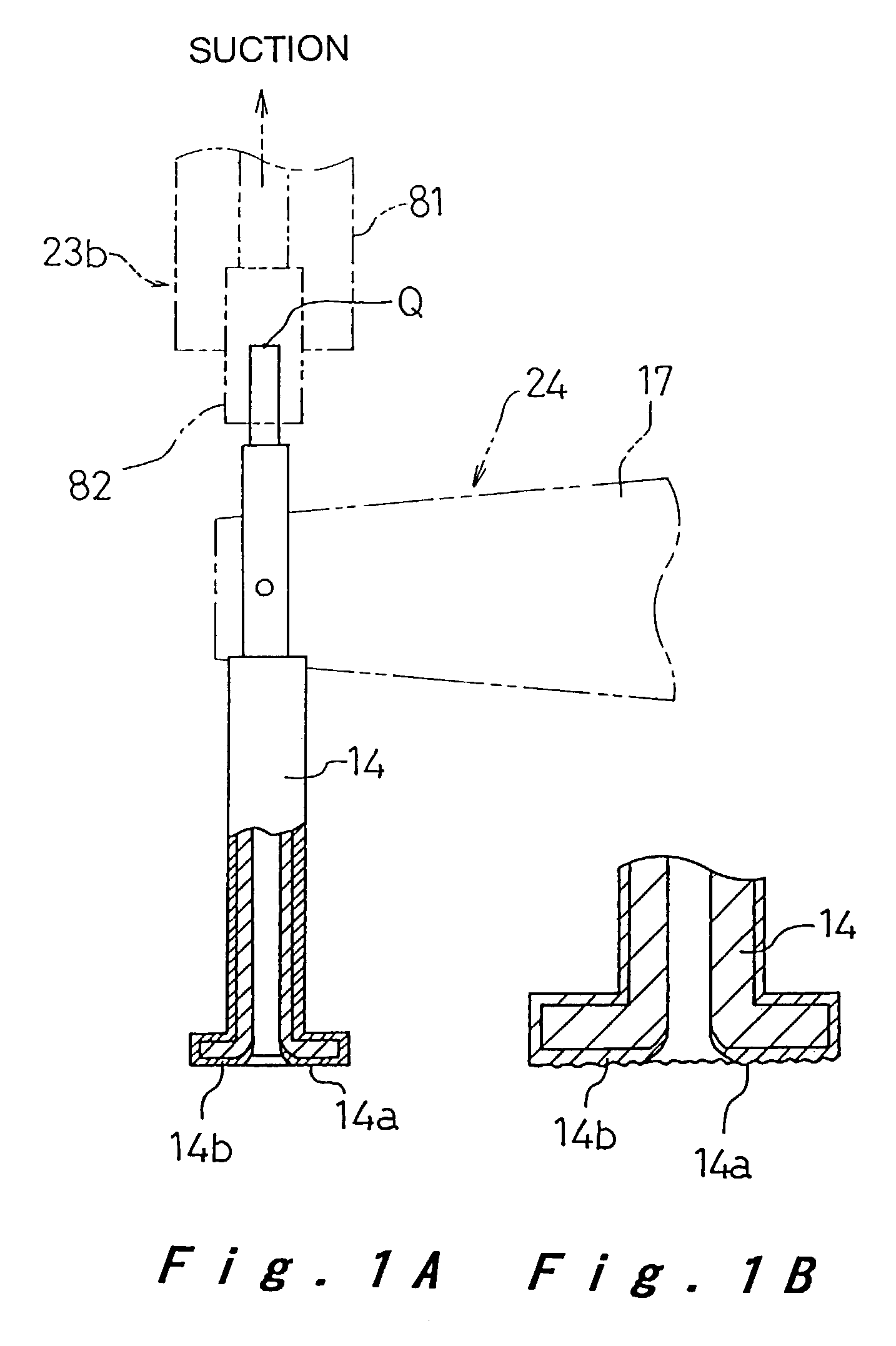
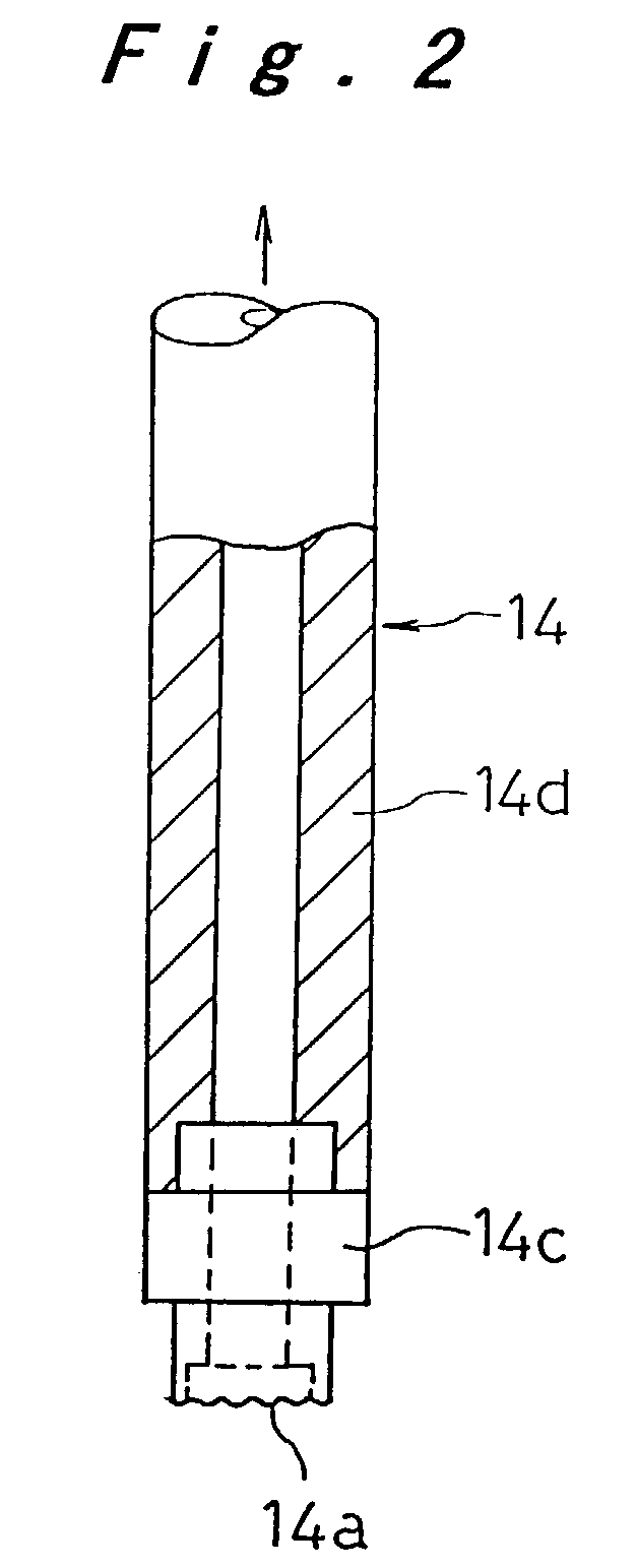
[0032]Preferred embodiments of a component mounting suction nozzle and a component mounting method and apparatus of the present invention will be hereinafter described with reference to FIG. 1 through FIG. 10.

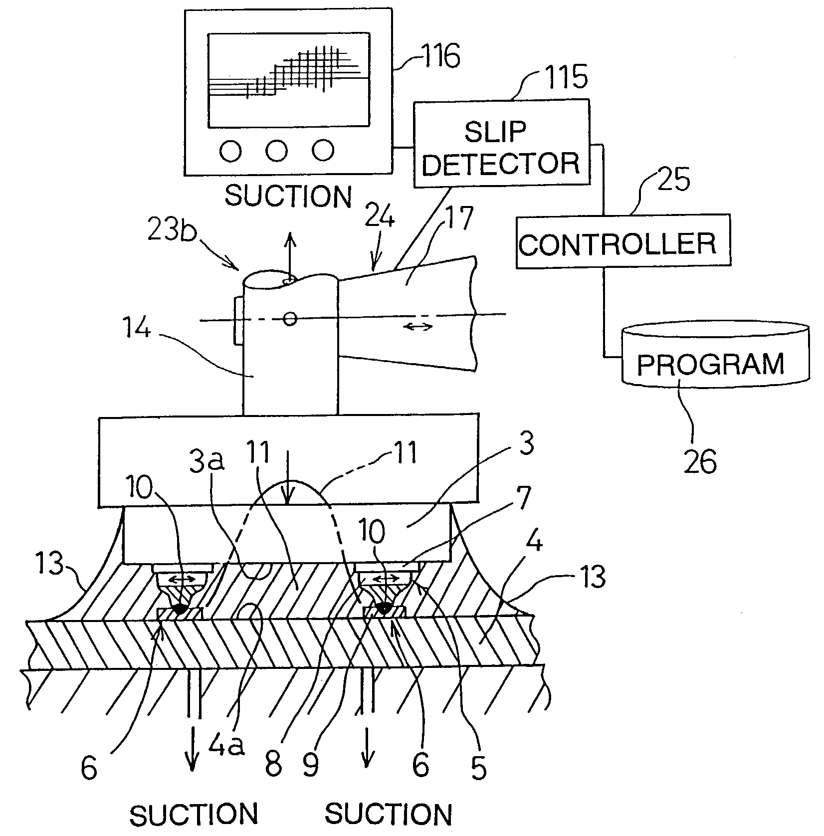
[0033]In this embodiment, bare IC chips 3 diced from a semiconductor wafer 1 on a dicing sheet 2 as shown in FIG. 5 and FIG. 10 are individually handled with a suction nozzle 14 as a component, and a printed wiring circuit board 4 shown in FIG. 1 is handled and referred to as an object. In particular, the embodiment describes a process of ultrasonic bonding for achieving electrical connection between IC chip 3 and circuit board 4 by melting and welding metallic interconnects 5, 6 on both of the chip 3 and board 4. By way of example, the metallic interconnect 5 of IC chip 3 is formed as a metallic bump 8 provided by wire bonding technique on an electrode fabricated by film-forming technique on a semiconductor wafer 1, and the metallic interconnect 6 of circuit board 4 is formed ...


PUM

PropertyMeasurementUnit
surface roughnessaaaaaaaaaa
roughnessaaaaaaaaaa
surface roughnessaaaaaaaaaa

Abstract

Component (3) is pressed onto a circuit board (4) so that their respective metal interconnects (5), (6) are in close contact with each other, and ultrasonic vibration is applied to the suction nozzle (14) holding the component (3). Friction is thereby generated between metal interconnects (5), (6) whereby the component (3) is bonded on circuit substrate. Suction nozzle (14) for handling components is made of stainless steel and has a working face (14a) provided with a hardened layer (14b), or alternatively, suction nozzle (14) may have a suction head (14c) having a working face (14a) made of cemented carbide. Working face (14a) of suction nozzle (14) is refined by polishing as required during the mounting operation.

Description

[0001]This is a divisional application of U.S. application Ser. No. 09 / 388,705 filed on Sep. 2, 1999 now abandoned.BACKGROUND OF THE INVENTION[0002]1. Technical Field of the Invention[0003]The present invention relates to a component mounting tool, and component mounting method and apparatus using this component mounting tool, wherein a component is mounted on an object by friction-bonding their respective metallic interconnects. In particular, it describes the process of manufacturing an electronic circuit substrate wherein an electronic component such as bare IC chip is mounted onto a printed wiring circuit board in electrical connection therewith by ultrasonic bonding.[0004]2. Description of Prior Art[0005]Bare IC chips are formed of a semiconductor wafer on which circuit patterns are fabricated using thin-film forming techniques and mounted on a printed board thereby manufacturing an electronic circuit board. For electrically connecting electrodes prefabricated with circuit patt...

Claims


Application Information

Patent Timeline
Patent Type & Authority Patents(United States)
IPC IPC(8): B23P19/00H05K13/04H01L21/00H01L21/60H01L21/683
CPCH01L21/67144H05K13/0408H01L24/75H01L21/6838Y10T29/53178H01L2224/16225H01L2224/32225H01L2224/73204Y10T29/49144Y10T29/4913Y10T29/53174Y10T29/49142H01L2924/00H01L2224/05568H01L2224/05573H01L2924/00014H01L2924/14H05K13/0409H01L2224/05599
Inventor HIGASHI, KAZUSHIMINAMITANI, SHOZOKANAYAMA, SHINJITAKAHASHI, KENJI
Owner PANASONIC CORP
Why Eureka
Try Eureka