Pre-charge apparatus and method for controlling startup transients in a capacitively-coupled switching power stage

a technology of capacitively coupled switching power stage and pre-charge apparatus, which is applied in the direction of electronic switching, amplifiers with semiconductor devices/discharge tubes, dc amplifiers with modulators, etc., can solve the problems of increasing the parts count and cost of the circuit, undesirable transients, and damage to the load

Active Publication Date: 2007-05-29
CIRRUS LOGIC INC
View PDF6 Cites 39 Cited by
  • Summary
  • Abstract
  • Description
  • Claims
  • Application Information

AI Technical Summary

Problems solved by technology

In amplifier applications, this transient is undesirable, as it is heard through speakers as a “pop” or “click” and in extreme cases may cause damage to the load.
The resistor divider must typically be provided outside of an integrated circuit power amplifier, and thus increases parts count and cost of the circuit.
If there is no DC feedback from the output, the offset will remain at the output during operation, affecting performance of the amplifier.
The resistor technique is also unsuited for automotive applications in which the current drawn through the resistors is continuously present even if the amplifier is producing no output signal.
In general, the presence of the resistor divider lowers the power efficiency of the amplifier.
The resistance of the divider must be reasonably low in order to keep the startup time short, so the lower resistance leads to high sink currents through the divider.
However, the technique disclosed therein does not so much control the startup transient, but rather reduces the output drive level during the unstable period of startup in the switching output stage.

Method used


Image

  • Pre-charge apparatus and method for controlling startup transients in a capacitively-coupled switching power stage
  • Pre-charge apparatus and method for controlling startup transients in a capacitively-coupled switching power stage
  • Pre-charge apparatus and method for controlling startup transients in a capacitively-coupled switching power stage

Examples


Embodiment Construction

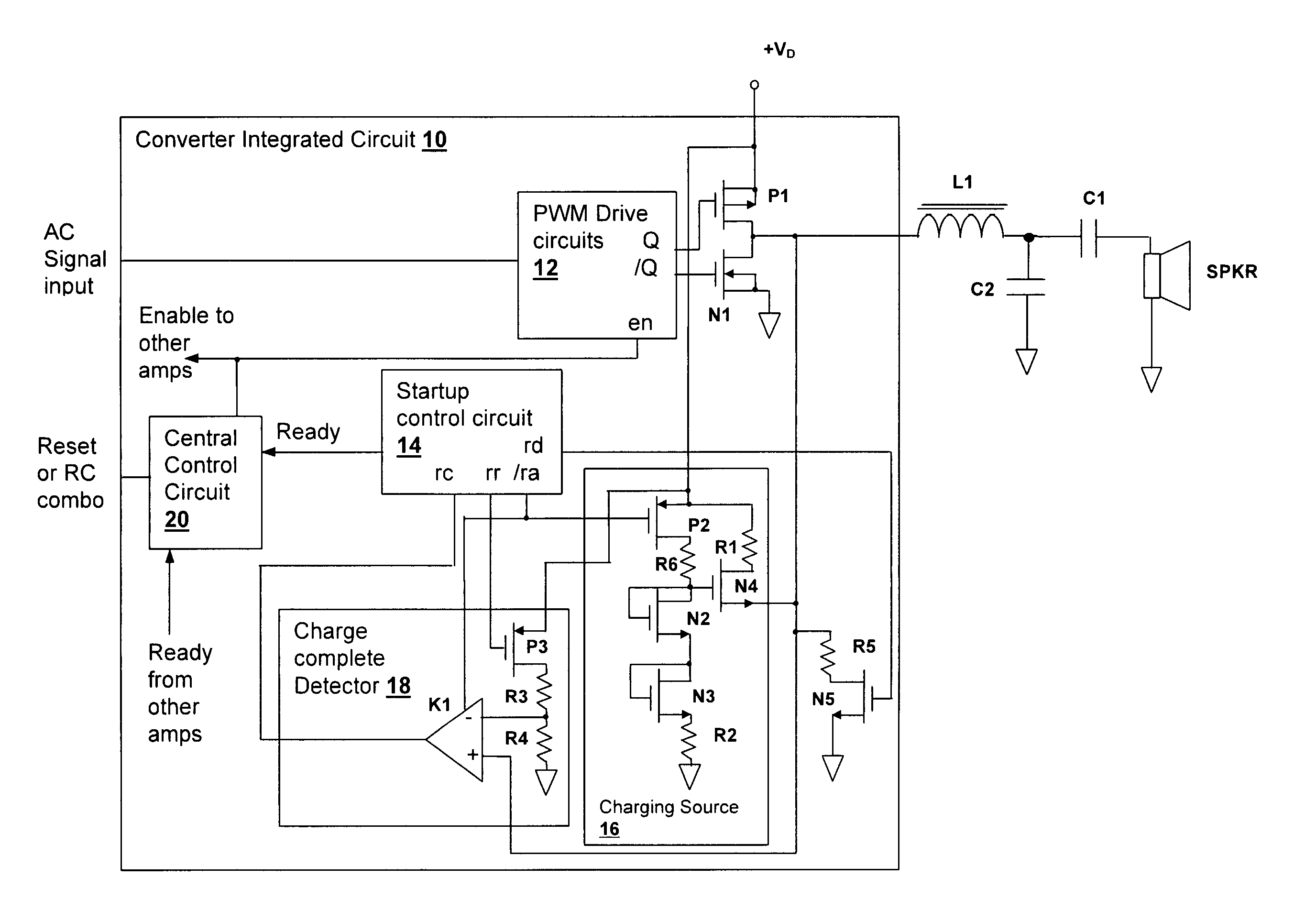
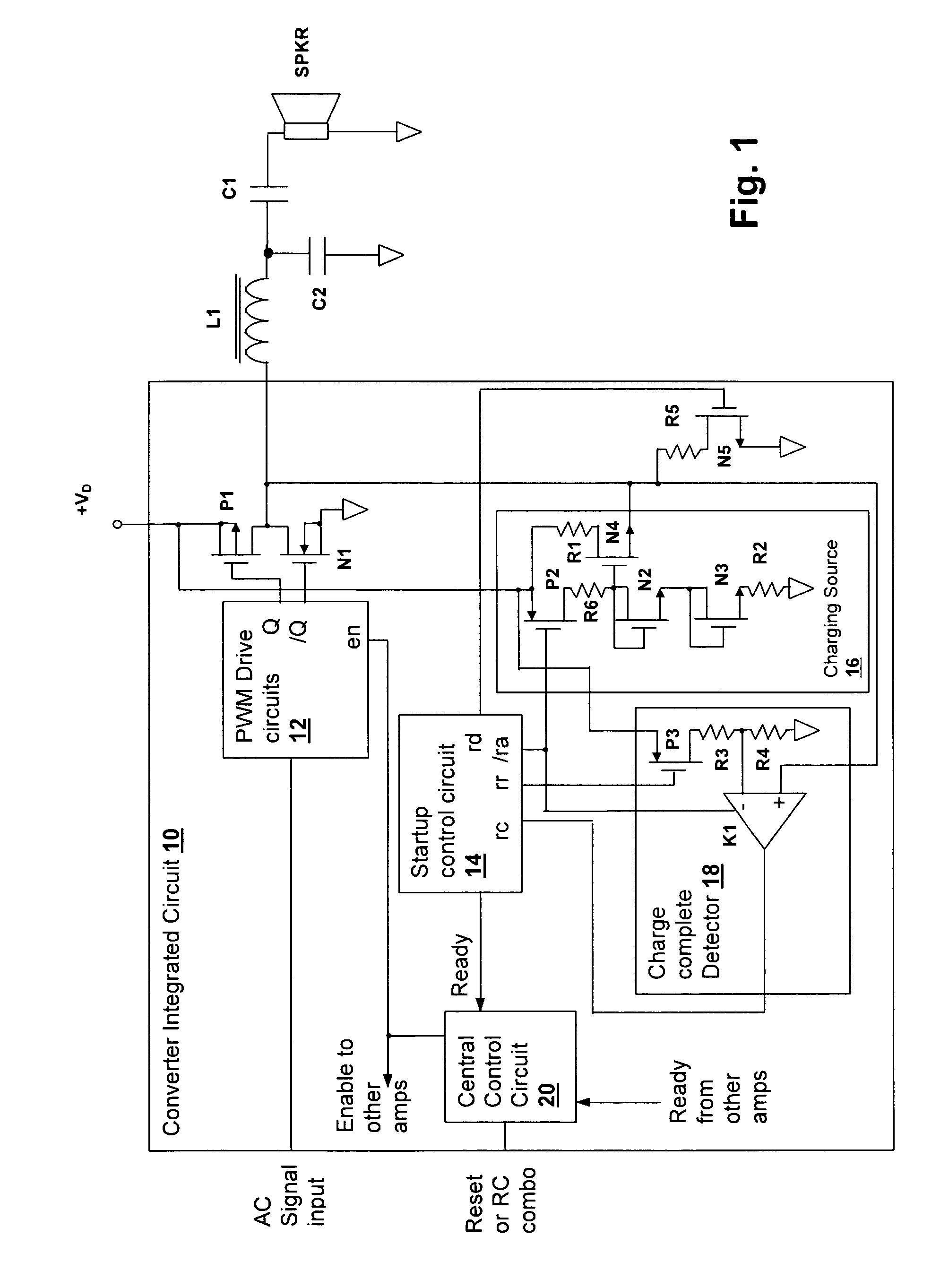
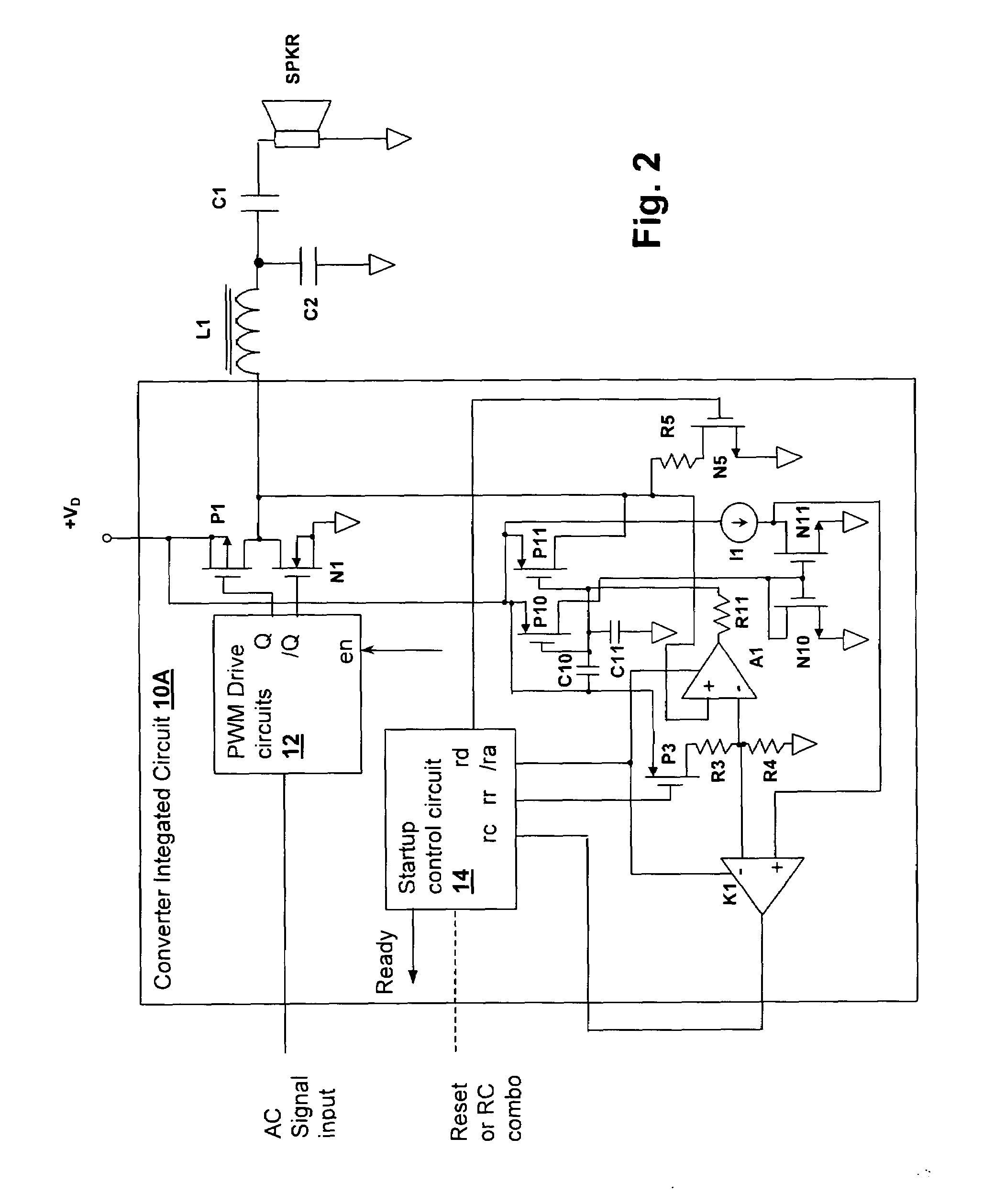
[0020]The present invention encompasses a circuit and method of operation that pre-charge a coupling capacitor that couples an output terminal of an AC output switching power converter, such as a Class D power amplifier, to a load. The capacitor is pre-charged to an operating point, which is generally the midpoint of the power supply swing of the output terminal at full load / full power. In essence, the DC operating point is dictated by the quiescent pulse width of the converter, which is chosen for maximum dynamic range in an amplifier design. The charging is performed via a controlled source from single power supply rail so that the switching converter does not present an unstable or uncontrolled transient behavior at the converter output which may cause audible “popping” at the output of an amplifier and possibly cause damage to the converter load. The single rail source causes the capacitor to charge quickly, as opposed to prior art solutions that feed current from both power sup...


PUM


Abstract

A pre-charge apparatus and method for controlling startup transients in a capacitively-coupled switching power stage provide lower cost and improved startup transient performance in Class D amplifiers, as well as in other AC power converter applications. A charging source is activated at startup to control the charging of an external capacitor from a single power supply rail to an operating point voltage equal to the average DC output of the switching circuit, while a control circuit disables the output power stage of the switching converter. The current source may be a constant-current source and / or may be controlled via feedback from the voltage or current at the output terminal of the converter to taper the current level to more accurately control the charging. A discharge circuit can also be provided to discharge the output terminal to an opposite power supply rail before commencing the controlled charging.

Description

BACKGROUND OF THE INVENTION[0001]1. Field of the Invention[0002]The present invention relates generally to integrated circuit power converters for providing an AC power output, and more specifically, to circuit and method for managing startup transients in the AC output.[0003]2. Background of the Invention[0004]AC output switching power converters are currently in widespread use. In particular switching power converters are commonly used in automotive amplifiers and other amplifiers in which a high power output is produced from an available DC voltage that is too low to deliver the desired power to a fixed impedance load. Switching power converter amplifiers, sometimes referred to as Class D amplifiers, also have higher efficiency than linear amplifiers, making them well suited for battery driven applications and applications where power dissipation in the form of heat is a problem, such as very high power professional audio applications, as in concert halls.[0005]Another applicatio...

Claims


Application Information

Patent Timeline
Patent Type & Authority Patents(United States)
IPC IPC(8): H03F3/38
CPCH03F1/305H03F3/2173H03K17/165H03K17/6872H03F2200/03H03F2200/351H03F2200/393
Inventor JIANG, JIANDONGZHANG, LINGLIGABORIAU, JOHANNMELANSON, JOHN L.
Owner CIRRUS LOGIC INC
Why Eureka
Try Eureka