System and method for cross correlation receiver

a receiver and cross-correlation technology, applied in the field of detection objects, can solve the problems of inability to determine the coherence between the receivers, the fluctuation of the amplification gain of the correlative receiver is usually not compensated, and the antenna and other microwave components located in front of the correlator contribute a small amount of noise, so as to achieve the effect of reducing the noise, reducing the noise, and reducing the nois

Inactive Publication Date: 2007-05-29
LOCKHEED MARTIN CORP
View PDF7 Cites 14 Cited by
  • Summary
  • Abstract
  • Description
  • Claims
  • Application Information

AI Technical Summary

Benefits of technology

[0014]Many benefits may be achieved by way of the present invention over conventional techniques. For example, certain embodiments of the present invention provide a method for making radiometric measurements and computing the cross-correlation of two signals over a large input signal dynamic range. Some embodiments of the present invention provide high sensitivity, precision and functionality to perform extraction, separation and characterization of the coherence properties of weak and complex signals. Certain embodiments of the present invention can compute the real and imaginary parts of a complex cross-correlation measurement and a normalization factor, and accumulate the computation results. The cross-correlation between two input signals is a function of the relative time delay between the signals. Some embodiments of the present invention compensate for amplification gain fluctuations in receiver channels. Certain embodiments of the present invention mitigate the effects resulting from offsets in analog-to-digital converters used in a digital cross correlator. These embodiments use a low pass filter with zero responses at pre-determined spectral locations to mitigate the effects due to imperfections in analog-to-digital converters. Some embodiments of the present invention perform cross-correlation measurements with simple circuitry for performing integer multiplications involving +1 and powers of 2's. The various components of the cross correlation receiver may be fabricated on a single chip. Certain embodiments of the present invention can provide a cross correlation receiver with more channels at lower costs and higher speed than conventional technologies.

Problems solved by technology

In the conventional systems and methods, the antenna and other microwave components located in front of the correlator contributes a small amount of noise because of the finite temperature of these components.
But the fluctuation in the amplification gain of the correlative receivers is usually not compensated.
When the weak signals to be correlated are themselves sums of plurality of weaker signals, the task to determine the coherence between them can be quite challenging.
Conventional correlation receiver usually cannot effectively extract and separate the correlation properties among weak and complex signals.

Method used


Image

  • System and method for cross correlation receiver
  • System and method for cross correlation receiver
  • System and method for cross correlation receiver

Examples


Embodiment Construction

[0022]The present invention relates in general to detecting objects and / or areas. More particularly, the invention provides a method and system for signal correlation. Merely by way of example, the invention is described as it applies to correlating two signals, but it should be recognized that the invention has a broader range of applicability.

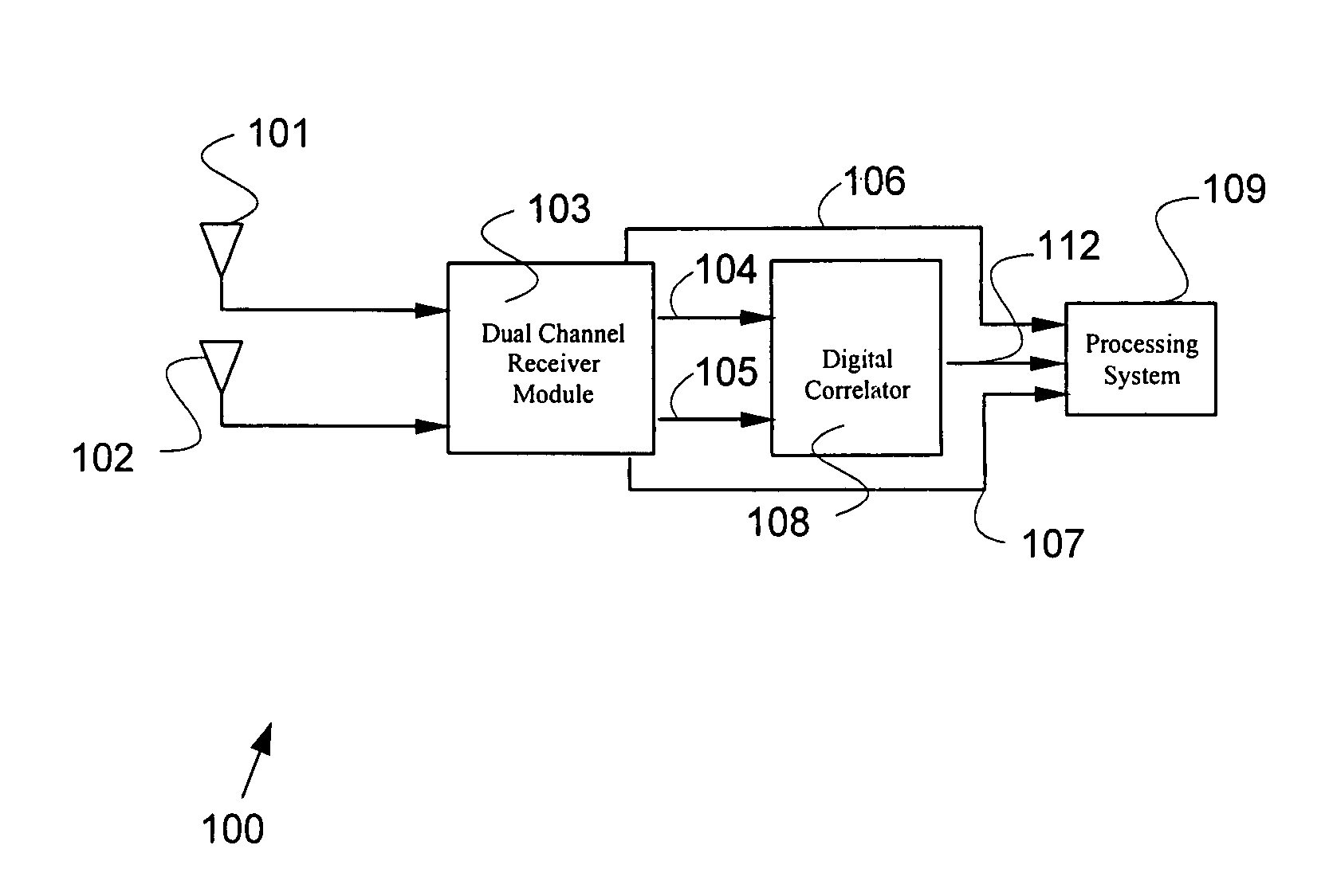
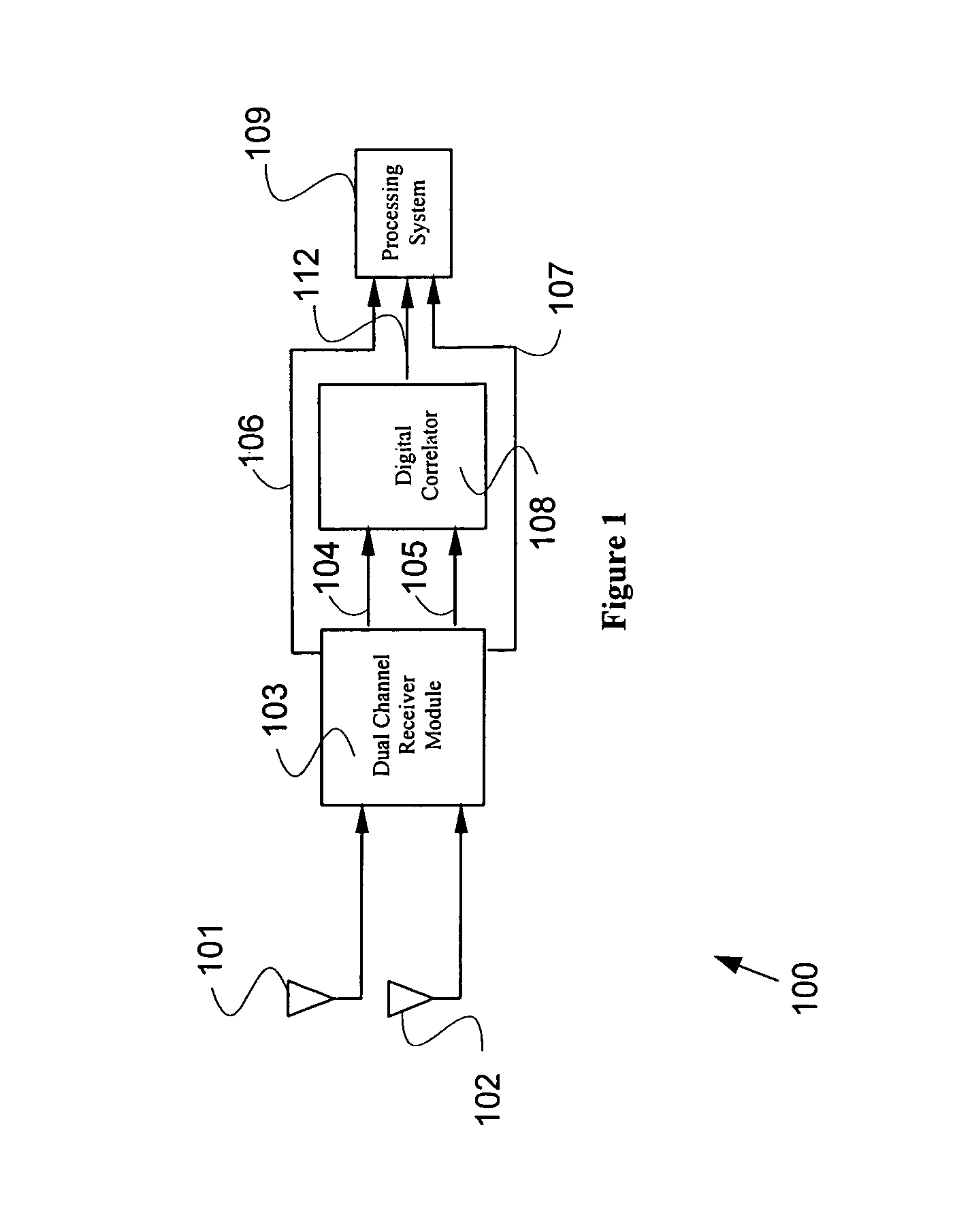
[0023]FIG. 1 is a simplified diagram for a cross-correlation receiver according to one embodiment of the present invention. This diagram is merely an example, which should not unduly limit the scope of the present invention. One of ordinary skill in the art would recognize many variations, alternatives, and modifications. A cross-correlation receiver 100 includes antennas 101 and 102, a dual channel receiver module 103, a digital correlator 108, and a processing system 109. Although the above has been shown using systems 101, 102, 103, 108, and 109, there can be many alternatives, modifications, and variations. For example, some of the system...


PUM


Abstract

A system and method for detecting signals. A system includes a first antenna configured to receive at least a first input signal and generate at least a first received signal, and a second antenna configured to receive at least a second input signal and generate at least a second received signal. Additionally, the system includes a receiver system configured to generate at least a first output signal, a second output signal, a third output signal, and a fourth output signal. Moreover, the system includes a correlation system configured to receive at least the third output signal and the fourth output signal and generate at least a correlation signal, and a processing system configured to estimate a cross correlated power level.

Description

CROSS-REFERENCES TO RELATED APPLICATIONS[0001]This application claims priority to U.S. Provisional No. 60 / 426,413 filed Nov. 15, 2002, which is incorporated by reference herein.BACKGROUND OF THE INVENTION[0002]The present invention relates in general to detecting objects and / or areas. More particularly, the invention provides a method and system for signal correlation. Merely by way of example, the invention is described as it applies to correlating two signals, but it should be recognized that the invention has a broader range of applicability.[0003]In radio astronomy, for example, the measurement of the cross correlation between two signals is required. A measurement configuration usually comprises of two spatially separated antennas pointing in the same direction to receive the microwave energy radiated by a selected radio star. The received microwave energy from the radio star is expected to be much weaker than the microwave energy received from the terrestrial thermal surroundi...

Claims


Application Information

Patent Timeline
Patent Type & Authority Patents(United States)
IPC IPC(8): H04B1/69H04B7/10
CPCH04B7/084H04B7/0865
Inventor LAM, LAWRENCE K.LOVINFOSSE, MICHAEL J.RAMSEY, BOBBY L.
Owner LOCKHEED MARTIN CORP
Why Eureka
Try Eureka