
Method for generating a simulated network using a graphical user interface

Active Publication Date: 2007-05-29
CISCO TECH INC
View PDF8 Cites 32 Cited by
  • Summary
  • Abstract
  • Description
  • Claims
  • Application Information

AI Technical Summary

Benefits of technology

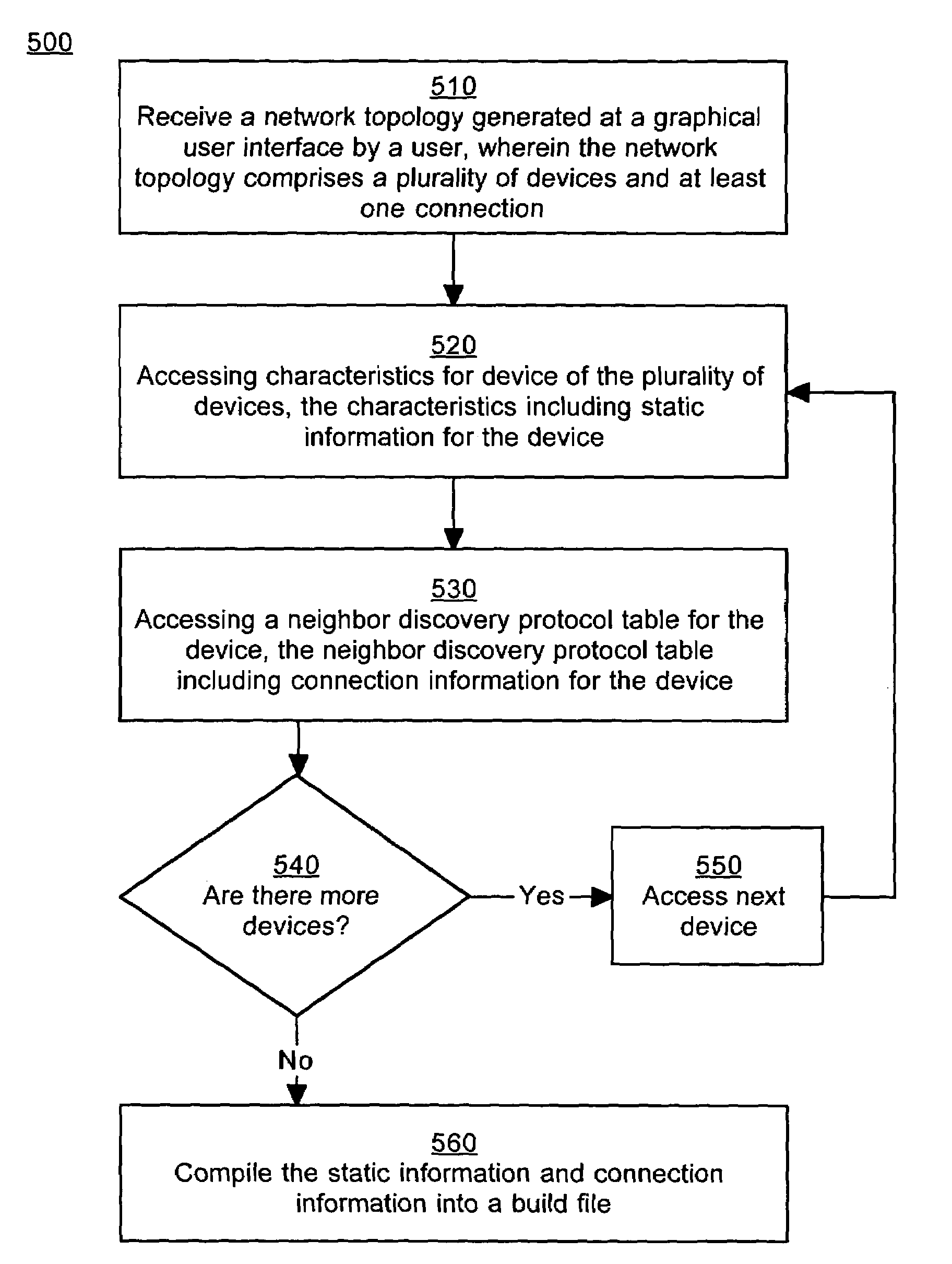
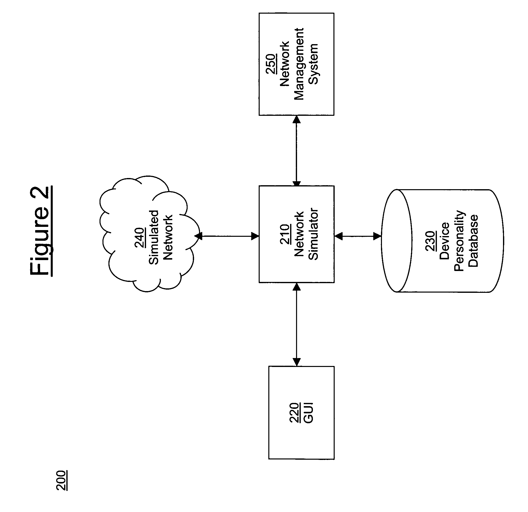
[0006]Accordingly, a need exists for method or system that allows a user to easily select devices of a network and place connections between the devices of a simulated network using a graphical user interface. A need also exists for a method or system that satisfies the above need, and provides a user with easy customization of the devices and connections of the simulated network. Furthermore, a need exists for a method or system that satisfies the above needs, and automatically generates the simulated network based on the devices and the connections.

Problems solved by technology

In a large enterprise with a large number of computing devices, the networking infrastructure can be extraordinarily complex.
However, due to security and network disruption concerns, enterprises are no longer open to this sort of testing.
However, this assumption is not always valid, as network complexity gets much greater in as the number of devices increases.
For simulating a large network of several thousand devices this is very time consuming, thereby consuming substantial human and financial resources of the enterprise.

Method used


Image

  • Method for generating a simulated network using a graphical user interface
  • Method for generating a simulated network using a graphical user interface
  • Method for generating a simulated network using a graphical user interface

Examples


Embodiment Construction

[0019]Reference will now be made in detail to the preferred embodiments of the invention, examples of which are illustrated in the accompanying drawings. While the invention will be described in conjunction with the preferred embodiments, it will be understood that they are not intended to limit the invention to these embodiments. On the contrary, the invention is intended to cover alternatives, modifications and equivalents, which may be included within the spirit and the scope of the invention as defined by the appended claims. Furthermore, in the following detailed description of the present invention, numerous specific details are set forth in order to provide a thorough understanding of the present invention. However, it will be apparent to one skilled in the art that the present invention may be practiced without these specific details. In other instances, well-known methods, procedures, components, structures and devices have not been described in detail so as to avoid unnece...


PUM


Abstract

A method for generating a simulated network using a graphical user interface (GUI). A network topology generated at a GUI by a user is received, wherein the network topology includes a plurality of devices and at least one connection between devices. A build file describing the network based on the network topology is automatically generated. A user is able to create and edit a simulated network through the GUI, thereby obviating the need for manually coding a simulated network. Large simulated networks can be quickly created, edited and maintained.

Description

FIELD OF INVENTION[0001]The present invention relates to the field of computer network simulation. Specifically, the present invention relates to a method for generating a simulated network using a graphical user interface.BACKGROUND OF THE INVENTION[0002]In a large enterprise with a large number of computing devices, the networking infrastructure can be extraordinarily complex. For example, a network of a large enterprise may include five to ten thousand devices. Network management systems are typically employed to monitor the network in order to ensure that the network is functioning properly. CiscoWorks by Cisco Systems is an example of a network management system.[0003]In order to ensure proper functioning of a network management system, it is necessary to test the network management system while connected to a network. In the past, the network management system would often be connected to a network of an enterprise. However, due to security and network disruption concerns, ente...

Claims


Application Information

Patent Timeline
IPC IPC(8): G06F13/10
CPCH04L41/145
Inventor FELDSTEIN, JEFFREY B.RAISONI, TARUNWOOTON, DONALD T.
Owner CISCO TECH INC
Learn More